[Trade Journal]
Publication: Western Electrician
Chicago, IL, United States
vol. 27, no. 22, p. 347-355, col. 1-3
The Plant of the St. Croix Power Company
of Wisconsin.
BY HENRY FLOY.
INTRODUCTORY.
The considerable number of high-tension, long-distance transmission plants already in successful operation, might not render the completion and starting of a 25,000-volt plant of any particular interest, except that in all engineering work, and especially in electrical lines, the "newest" usually means something of a change from, and improvement upon, anything previously constructed. There are, however, some features, both hydraulic and electrical, connected with the plant of the St. Croix Power company, recently put into operation, which I think will prove of more than ordinary interest to the members of this Institute.
GENERAL DESCRIPTION.
About two years ago the St. Paul Gas Light company of St. Paul, Minn., owing to increasing business, the depreciation and antiquity of its generating apparatus and the expense of operating four distinct stations, foresaw that it must build a single modern and larger steam-generating plant or arrange for securing current by means of long-distance transmission through the development of one or more of the waterpowers within reasonable distance of St. Paul.
Upon investigation it was found that 27 miles east of St. Paul, on Apple River, in the state of Wisconsin, there was a natural fall of about 30 feet. Above the fall a dam could be built to a height of 47 feet, thus affording, with a slight drop in the river below the fall, a total head of 82 feet. Apple River is fed from innumerable springs and some 25 lakes in northwestern Wisconsin, and in consequence its discharge is remarkably uniform the year around. With the head afforded, the minimum flow of water in the stream would yield about 2,000 horsepower continuously, and during most of the year nearly twice that amount. By the building of a dam, a large reservoir would be formed, from which the impounded water could be drawn in any quantity necessary to carry the peak of any load in St. Paul, provided sufficient capacity was installed in water-wheels, generators and transmission line. It was thus demonstrated to the St. Paul Gas Light company that the power that could be made available at Apple River Falls by a development of the character just outlined, would permit not only the complete shutting down of its four steam plants and avoid the necessity for building a modern steam plant, but also provide it with nearly twice the salable output of its old stations.
Accordingly, about a year and a half ago, there was organized under the laws of the state of Wisconsin the St. Croix Power company. This company is friendly to the St. Paul Gas Light company, and to the latter the former contracted to sell all the current it could generate by the development of a power plant at Apple River Falls.
GENERATING STATION.
The generating station is a fireproof structure of brick and iron, about 140 feet by 50 feet, divided longitudinally by a partition wall, thus separating the wheel room from the dynamo room. (See Fig. 1, next page.)
In the wheel room are four main sets of water wheels, space being reserved for the fifth unit, which may be added later. Each set consists of two 36-inch special Victor wheels, mounted horizontally in a nine-foot, cylindrical, steel wheel chest from which they discharge through a six-foot draft tube, eight feet long. Each pair of wheels is, of course, on a single shaft, which extends through the end of the wheel chest built into the partition wall, and is direct-connected to a 750-kilowatt generator. Each wheel chest is supplied from the penstock by its own feeder pipe, in which is located a 56-inch gate valve operated from a shaft driven by a 7 1/2-horsepower electric motor. Each wheel chest is surmounted by an automatic spring relief valve having an opening 12 inches in diameter. There are two exciter wheels, each direct-connected to a 30-kilowatt, direct-current generator. The exciter wheels have their own branch feeder pipes, wheel chests and separate gate valves.
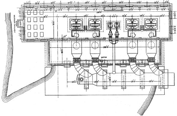 |
| Fig. 1. St. Croix Power Plant. Plan of Generating Station. |
The waterwheel governors are of an improved type of the Geissler pattern. They are guaranteed to maintain the speed within three per cent. of normal tor any instantaneous change in load not exceeding 25 per cent. of the load at the moment of variation. The governors are electrically controlled, being operated by the 125-volt exciter current.
All the alternators are 750-kilowatt, three-phase, 800-volt, 60-cycle, revolving-armature, separately excited machines, running at 300 revolutions per minute. They will carry full load continuously without heating more than 40 -degrees C. above the temperature of the surrounding air, and have an inherent regulation slightly under five per cent. on non-inductive load.
The direct-current exciters are shunt-wound, operating at 925 revolutions per minute, and each machine is of sufficient capacity to excite five 750-killowatt alternators.
Across the lower end of the dynamo room is the marble switchboard, consisting of an exciter panel, four generator panels, two transformer panels and a local-service panel. The exciter panel is supplied with the usual instruments, but the alternator panels are each equipped with one main oil switch, in series with two triple-pole, quick-break jaw switches, for throwing the machine on to either two sets of bus-bars. At the top of the panel is an ammeter, an indicating wattmeter, and a held ammeter, with the usual synchronizing lamp, held switch and voltmeter plug. The transformer panels will each be provided with an induction recording wattmeter, a single three-phase oil switch of special design, having a capacity of 1,500 kilowatts at 800 volts, and a potential indicator which enables operators at the generating-station switchboard to determine the voltage at the St. Paul sub-station, regardless of the power factor of the load or the drop in the line.
A brief description of this type of potential indicator may not be amiss. Across the terminals of the main transformer leads is connected a small transformer supplying in its secondary circuit, an electromotive force in step with and proportional to that of the generator. In series with the main transformer leads is a small series transformer, which supplies in its secondary circuit a current always in step with and proportional to its primary current. The secondaries of the two transformers are connected in series through an inductive resistance and an ohmic resistance. Both the inductive resistance or reactance and the ohmic resistance are so adjusted that for a given current through them, their respective electromotive forces have the same value relative to the electromotive force of the potential transformer as the reactance and resistance electromotive forces of the transmission circuit have to the electromotive force of the generator. Therefore, the local reactance and resistance electromotive forces reduce the electromotive force supplied by the potential transformer to a potential indicator connected in this local circuit, in the same proportion as the line reactance and resistance electromotive forces cut down the generator voltage, and thus the potential indicator at the generating station is made to indicate the voltage at the point of distribution.
The local service switchboard panel is equipped with switches for controlling the electric heaters by which the power house is warmed, also the incandescent and arc-lighting circuits and the motors driving the blowers.
There have been installed six air-blast transformers of 500 kilowatts' capacity each, which step the voltage up directly from 800 to 25,000 volts. As operated, the transformers are connected in two sets of three each, with "Y" connections. The low-tension side of each set of transformers is joined directly with the transformer panel switches, and the high-tension side with Westinghouse "spider" switches, through the use of which either bank of transformers may be connected to either or both of the transformer circuits.
All the electrical apparatus in the power plant was furnished by the General Electric company, except the high-tension switches and the alternating-current arc lamps, which latter were purchased from the Manhattan General Construction company. These lamps are of the enclosed type and require 0.6 amperes. They are operated in series directly from the 800-volt bus-bars, there being eight lamps and regulator in each circuit.
A 20-ton hand crane, traveling the entire length of the dynamo room, affords a convenient method for handling the heavy machinery.
25,000-VOLT OVERHEAD AND UNDERGROUND
TRANSMISSION LINE.
Two three-wire, three-phase transmission circuits, each consisting of 24 1/2 miles of overhead, bare copper wires, and three miles of underground cables connect the generating plant with the distributing station in St. Paul.
Both overhead circuits are carried on a single line of poles. The wires of each circuit are on one side of the poles and are supported so as to be at the verticals of an equilateral triangle having 24 inch sides. The conductors are of No. 2, B. & S. medium hard-drawn copper wire, carried on glass insulators of the "Provo type" the same as those used on the 40,000-volt transmission in Utah. The insulators are seven inches in diameter and have a triple petticoat. They are mounted on special locust pins, boiled in paraffine, carried on two four-inch by five-inch Oregon fir cross-arms. The poles are mainly of Oregon fir and are spaced not more than 110 feet apart. No poles less than 30 feet in length and eight inches in diameter at the top are used. Poles, of minimum length are planted 5 1/2 feet in the ground and six inches deeper tor every additional five feet in their length. The line was designed to be practically level, irrespective of configurations in the earth's surface. The corners and angles in the line are reduced to as few as possible, consistent with securing a right-of-way at a reasonable price; no angle in a conductor at any insulator is less than 165 degrees, thus avoiding any dangerous tendency to break the pins. In making a right-angle turn special construction is used (see Fig. 2), affording seven points of support for each wire. For slight turns two or three poles, as may be required, are set 10 feet apart, but no more than one insulator per wire is allowed on a single pole.
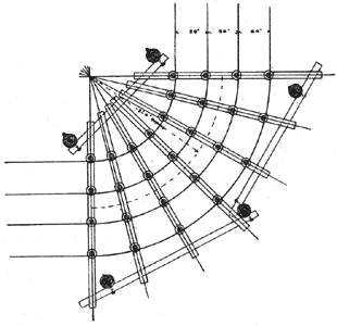 |
| Fig. 2. St. Croix Power Plant. Special Corner Construction in Pole-Line Work. |
The transmission line really takes its beginning at the terminals of the step-up transformers in the dynamo room of the generating station, whence it passes through the Westinghouse high-tension switches into a brick lightning-arrester house abutting against the end of the power house. Here are located choke coils and lightning arresters. From the arrester house the wires pass out through circular openings in the wall, which are sheltered by a gabled roof and run thence in a general western direction to a similar arrester house in the city of St. Paul, where they terminate in the heads of the underground cables.
No special engineering difficulties were met with in the construction of the aerial line, except in crossing the St. Croix River, which is about half a mile wide, with precipitous banks, 100 or more feet in height. Advantage was taken of a bridge built by the Wisconsin Central railway, and long oak pieces were fitted between the ties every 50 feet through- out the length of the bridge. These oak pieces project about 20 feet beyond the edge of the bridge and on them the six wires are carried in a horizontal plane. To nullify any bad effects of the ironwork in the bridge, the wires of each circuit are spiraled three times in the length of the bridge.
As is usual with two parallel, three-phase circuits, one circuit is spiraled twice relatively to the other circuit, in addition, to the transpositions on the bridge, to prevent mutual induction.
Six feet below the power-transmission circuit, on a separate cross-arm, are carried two No. 10 galvanized-iron wires, which constitute the telephone line. The wires are transposed at every fifth pole, which very satisfactorily avoids any inductive effects in the line and results in very efficient telephone service.
There are two three-conductor, lead-covered cables, connecting the lightning-arrester house with the distributing sub-station located on Cedar street, in the very center of the business section of St. Paul. These cables are in four-hole McRoy vitrified-clay conduits laid in concrete. The conduits follow the grade of the streets, except where it was necessary to pass under a number of railroad tracks in a deep cut. Here, the conduits end in the top of a brick well about 50 feet in depth, down which the cables drop, passing from the bottom of the well in other conduits to another well on the opposite side of the tracks, through which they rise again to the conduits laid below the pavements of the street.
In considering the use of cables for 25,000-volt transmission underground, the writer found that a number of reputable manufacturers not only declined to bid on his specifications, but would not entertain any proposition for furnishing such cables, even under their own specifications. There were only two companies that would undertake the work, and accordingly a contract was entered into with these companies, one to furnish a rubber-insulated and the other a paper-insulated cable.
The specifications provided that the general design of both cables should be the same, that is, each conductor having an area of not less than 66,000 circular mils is composed of seven strands of copper wire enclosed in insulation, the three laid up in jute, and the whole enclosed in a jacket of the same insulating material as that used about each conductor. Outside of the jacket is the lead sheathing, one eighth inch in thickness, making the cable complete about 2 1/4 inches in diameter.
The National cable is insulated with paper treated with a secret compound. The insulation about each conductor is nine thirty-seconds inch in thickness. That of the enveloping jacket, four thirty-seconds inch thick. The covering of this cable is of lead, protected on the exterior by a coating of tin.
The insulation of the Safety cable is about a 35 per cent. compound of the best "old up-river" Para rubber seven thirty-seconds inch thick, around each conductor, wrapped with a drilled tape, served with jute, with the jacket five thirty-seconds inch thick. The sheathing of this cable is of lead, mixed with three per cent. of tin.
The contracts entered into with the above companies for cables included not only their manufacturing the cables and testing them to 40,000 volts in their factories before shipment, but also the installation of the cables complete ready for operation in the conduits in St. Paul. The contracts further include a guarantee for a period of five years protecting the purchaser against any breakdown in the cables, except those due to extraneous and mechanical injuries, and further permitting at any time during that period, the testing of the cables in situ, up to a potential of 30,000 volts. The writer's aim in having the contract for each cable awarded to a separate company was to secure the benefits of competition in promptness of delivery and perfection of manufacture. Furthermore, as underground work of such tension had never been attempted before there was some question as to whether rubber or paper would prove the more durable insulator under these conditions.
While, of course, the ultimate success of 25,000-volt underground transmission can only be determined by the lapse of time, and the action of high voltage in its effect on the insulation, nevertheless, the success in operating seems to have demonstrated the wisdom of the experiment, and great credit must be given to the companies for their co-operation in undertaking what had never before been attempted and what many manufacturers prophesied would result in failure.
The calculated resistance of each conductor between the generating and distributing stations is 23 ohms. The drop in voltage between the same points, for 3,000 kilowatts, delivered with a 90 per cent. power factor and 25,000 volts' initial potential, figures 7.7 per cent., operating both lines in multiple, which will be the usual practice.
SUB-STATION AND APPARATUS.
The distributing station in St. Paul is an iron and brick building, designed to contain the necessary apparatus for reducing the potential and controlling and transforming the energy received over the transmission line, for distribution in the city of St. Paul. The building is 50 feet by 70 feet, 2 1/2 stories in height. One-half of the building has a basement divided into two rooms; one, in which all the static step-down transformers and high-tension switches are located, is connected by a tunnel with the street conduits; the other serves as a toilet room and place in which to locate the apparatus for heating the station. The main floor is divided into three rooms open to the roof. The larger room, 50 feet by 50 feet, contains six 250-kilowatt rotary converters and two marble switchboards, extending along two sides of the room. The second room on this floor serves as a hallway to the main room, and affords a place in which to locate telephone box, etc. The third room is open from the roof to the basement, but is entirely cut off and separated from all the rest of the building, except for a single door from the hallway. This room is intended for a storage battery, which it is planned to install later.
Each conductor of two high-tension cables passing through the tunnel into the transformer room ends in one terminal of a single-pole knife switch, to be operated only when current is off the line and installed to permit convenient testing of cables, etc. The other terminal of each switch is connected to a high-tension bus-bar, from which taps are taken off to the high-tension switches controlling the circuits to the different sets of transformers. The ends of the cables are also connected to static discharges, which are merely, a number of standard lightning arresters, connected in series.
The high-tension bus-bars and their taps to the high-tension switches and from the switches to the transformers are single conductors, insulated with one-fourth inch of best Para compound, and guaranteed to withstand 25,000 volts continuously. The conductors are carried in conduits made of wood pulp, indurated with asphaltum, manufactured by the Fiber Conduit company. The conduits are guaranteed to withstand 20,000 volts without breaking down.
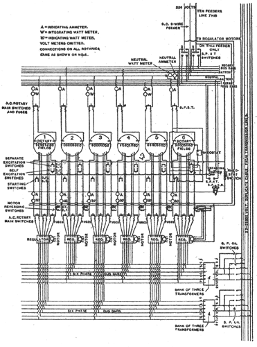
The high-tension oil switches are of the single-pole, three-break type, operating under oil and designed to break 25,000 volts and 50 amperes. The switches are closed by hand, but opened by the releasing of a latch controlled by a local circuit from the main switchboard upstairs. There are 24 high-tension switches in all 12 connected with each set of the cable bus-bars. As all high-tension work is three-phase, this necessitates the closing of three switches to connect any set of transformers with either set of bus-bars. (See diagram of connections, Fig. 3.)
There are four banks of static step-down transformers two banks consisting of three 22,500 to 78-volt, oil-cooled, 300-kilowatt, three-phase to six-phase transformers, and two banks of two 22,500 to 2,100-2,700-volt, oil-cooled, 200-kilowatt, three-phase to two-phase transformers.
Each one of the 300-kilowatt transformers has a single winding on the primary, and two entirely distinct and separate windings on the secondary. By connecting three of these transformers in a set, the three-phase to six-phase transformation is effected. One set of these transformers supplies current to the rotary converters, operating between the positive and neutral wires, and the other set to those rotaries operating between the neutral and negative wires of the Edison three-wire system of distribution throughout the city. There is kept on hand a spare transformer in case of breakdown, but as all transformers in the sub-station are connected in delta, it is perfectly feasible to successfully operate, although there are but two transformers of a set connected in circuit. In fact, this was the method of operating for the first few weeks after starting the plant, and until the remainder of the transformers were received.
The two identical sets of three-phase to two-phase, 200-kilowatt transformers provide for the alternating-current distribution throughout the city. On the front of each transformer case is mounted a quick-break, multipoint switch, connected with leads brought out from the secondary windings of the transformers. The movement of the switch throws more or less turns of the secondary in circuit, and thus adjusts the potential in steps of 21 volts to any desired point between 2,100 and 2,700 volts.
The plan of operating from the generating station is to maintain, irrespective of load or line loss, the potential on the high-tension bus-bars in the sub-station, at 22,500 volts, as shown by the potential indicators previously described. This potential gives 78 volts for the rotary converters, which potential may be varied seven volts either up or down, by use of inductor regulators, of which there is one for each rotary. In a similar manner, the potential for alternating-current distribution is regulated by the setting of the multipoint switches at any point between 2,100 and 2,700 volts, depending on the load.
The use of six-phase transformers and converters is novel. The reason for the adoption of six phases instead of three phases was to secure the advantages of reduction of copper losses in the armature, and the accompanying reduction of temperature and its better distribution. At first sight, it might seem that the increased complexity involved in the use of six phases would not counterbalance the advantages to be gained. Practically, however, the use of six rings and the necessary additional taps to the windings on the armatures amounts to nothing in the operation of the machines. The dividing of the secondary windings on the transformers for two independent circuits results in no complication or expense. On account of the large current, the use of six conductors between the transformers and switchboard and between the switchboard and rotaries, was necessary, whether three-phase or six-phase machines were installed. The switchboard is practically the same for either number of phases, except that the number of main switches was increased from two to three. This disadvantage, however, may be disregarded when a decided increase in the capacity of the rotaries is secured. The rotaries are ordinarily started from the direct-current end, but are equipped with breakdown field switches and designed for starting from the alternating-current end, where necessary.
 |
| Fig. 3. St. Croix Power Plant. Wiring Diagram for Six-Phase Apparatus and Rotary Converters. |
The alternating-current switchboard is about 35 feet in length and eight feet in height.
On the extreme left is a relay panel, through which current is usually distributed by means of four-conductor cables, to one of the old steam-generating plants. This plant will be used as a relay station, and in case of a breakdown in the water-power transmission plant, current will be supplied from it to the sub-station. The second panel from the left is a transformer panel connecting either set of the static transformers, supplying current for alternating-current distribution to either of the two sets of four bus-bars. Each two-phase circuit is provided with two ammeters, two recording watt-meters, a four-pole oil switch and fuses. On this panel are also eight small double-pole switches, each of which controls the current to the magnets, releasing the latches of three of the 25,000-volt switches.
The panel next adjacent on the right controls the power-distributing, two-phase circuit. The five following panels each control two single-phase, alternating-current lighting circuits. Each of these panels is provided with an ammeter, automatic oil circuit-breaker and oil switch, in series with plug switches. There will be noticed a number of holes in these panels which are designed for the plug switches, permitting the plugging of any single-phase feeder on to any pair of the eight bus-bars. The double-pole plugs used are shown in the illustration lying in a pile at the foot of two of these panels.
Next come six alternating-current rotary panels, supplying current at 78 volts to the alternating-current end of the rotary converters. These panels are provided with three two-pole switches for the six-phase circuit, also indicating wattmeter and main ammeter, thus giving an indication of the power factor of the load. There is also the handle of the field rheostat, a direct-current, starting switch, double-pole, double-throw field switch, synchronizing plug and lamp and a small direct-current, two-pole, double-throw switch controlling the motor actuating the six-phase inductor regulators. The inductor regulators are placed on the floor directly behind the alternating-current rotary panels.
The extreme right-hand panel contains a double-throw, direct-current switch, a starting-rheostat switch and an automatic circuit-breaker, through which is supplied and controlled the direct current from the Edison system used in separately exciting and starting the rotary converters. On this panel there are also three multipoint voltmeter switches, through the use of one of which the voltage of any of the Edison feeders or rotary-converter bus-bars at the other switchboard may be shown on the direct-current voltmeters hinged on the right of the board. The other two voltmeter switches in conjunction with the swinging alternating-current voltmeters shown on the left of the alternating-current rotary panels permit the reading of the potential of any of the alternating-current feeders or alternating-current ends of the rotary converters.
The direct-current, three-wire switchboard, about 18 feet long and eight feet high, is at right angles to the board just described. It consists of eight panels, three for the direct-current end of the rotaries and the remainder for the feeders of the Edison three-wire distributing system.
Each direct-current rotary panel controls the current from a pair of rotaries operating together on the three-wire system.
The Edison feeder panels are provided with single-pole, four-way switches of special design, which permit the throwing of any feeder on any one of four sets of bus-bars. Three of the bus-bars may be supplied at different potentials from each of the three pairs of rotaries. The fourth set of bus-bars is designed for use in connection with the storage battery, when same shall be installed. It will thus be seen that great flexibility in distributing potential is attainable, for, if necessary, the battery can be used independently of the rotaries, making a fourth and independent voltage available for feeder service.
The static transformers and rotary converters were furnished by the General Electric company. The General Incandescent Arc Light company furnished the high-tension switches and both switchboards, the latter being equipped with indicating instruments mainly manufactured by the Wagner Electric Manufacturing company.
TESTS.
A report of the tests of the hydraulic and electrical apparatus might prove commonplace, but the following, relating to the overhead transmission line and underground cables, may be of interest because little data has been published with regard to the charging current of overhead lines, and nothing whatever, as far as the writer is aware, regarding high-tension cables.
The first tests made were simply to ascertain whether the cables could carry the voltage under which they were to operate. The paper cable was first tested, the voltage being gradually raised to 30,400 volts. This was on the afternoon of October 14th, which, I believe, marks the date of any attempt to carry such high potential underground. The rubber cable was successfully tested about two weeks later in the same way.
In making measurements and in the following data on the charging current of overhead lines and cables, no allowance is made for any leakage current, as exhaustive and careful tests made on high-tension lines at Telluride by Mr. R. D. Mershon prove that, with proper insulators, there is no precipitation and, with the voltages here used, any leakage current is inappreciable.
The charging current was measured by placing in the high-potential circuit, a Stanley hot-wire ammeter reading from zero to 13 amperes. The Stanley meter was compared with a Weston portable ammeter reading from zero to 15 amperes, which had just been calibrated at the Weston laboratory. The difference in readings between the two ammeters was small, but corrected readings are given in the accompanying curves. The voltage readings were taken by a newly calibrated Weston portable volt-meter, connected to the secondary of a small transformer, having a ratio of one to 200, and designed and built especially for voltmeter measurements by the Pittsburg Transformer company. The voltmeter used was compared during the tests with another portable Weston voltmeter, with which it agreed closely. It was also compared with a General Electric switchboard voltmeter, and the practical correctness of the instrument used was verified.
The alternations of the generators supplying current for the charging tests were kept constant by maintaining the speed constant, as shown by a tachometer. No measurements were made as to the wave forms of the generators.
In making all charging-current measurements, only two generators were used. For supplying the current at the generating station, where most of the tests were made, one of the 300-revolution, General Electric generators there installed, was employed. which, by reason of the source of its power, could easily be kept at a uniform speed. At St. Paul, a Westinghouse revolving-armature, 400-revolution, 375-kilowatt. 60-cycle machine was used.
Measurements on both overhead lines showed that the charging current to either line was practically the same as that to the other. Furthermore, it was found that the charging current to one line was practically the same, whether both ends of the other line were left disconnected from everything, or whether its three conductors were tied together and connected to good ground.
From some few measurements, the charging current for the rubber cable was found to be a little more than double that of the paper cable. This result, from the standpoint of overcoming the reactance in the circuit, would make the use of a rubber cable the most desirable. The charging current for two wires of the three-phase circuit is appreciably less than when voltage is applied to all three conductors. It checks very closely with what would be expected as figured.
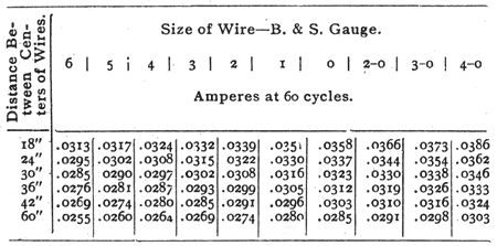
The following data on charging current, taken from the writer's note-book, may be convenient for reference, and it is therefore here included because it has never before been published.
CALCULATING CHARGING CURRENT
Two parallel wires: Length one mile: 10,000 volts:
Sine wave: Sixty cycles:
The current varies directly as the length of the line, the voltage and the cycles, so that the current for any given line and different voltage or cycles may be easily calculated:
 |
It is a pleasure to state that we have never had any trouble with resonance, harmonics or any other of those "bogies" which have proved in some instances destructive to apparatus and are a cause of disquietude to the engineer of almost any long-distance transmission plant, until after the same has been put into successful operation.
This paper would be incomplete without acknowledging the credit due to the writer's associate, Professor R. C. Carpenter of Cornell University, for his assistance and co-operation in designing the mechanical and hydraulic plant. Much praise should also be given Mr. L. W. Rundlett, our resident inspector and engineer on the mechanical and hydraulic work. through whose experience, patience and faithfulness, the results of the excellent concrete work were attained. Mention must also be made of Mr. J. L. Harper, who acted as our resident inspector on the transmission line and electrical work, and who is now serving as the general superintendent of the operating station at Apple River Falls. Mr. William De la Barre of Minneapolis advised with us from his wide experience in hydraulic matters, and Mr. W. A. Gordon of our own office has materially assisted in calculations and tabulations. Messrs. H. J. Gille and Fred R. Cutcheon, superintendent and engineer, respectively, of the electrical department of the St. Paul Gas Light company, and Mr. H. L. Doherty, president of the Denver Gas and Electric company, had much to do with the design of the sub-station switchboards. It should be stated that Mr. Doherty was the first engineer to recognize and appreciate the possibilities for the power development in Wisconsin and its transmission into St. Paul, Minn.
Abstract of paper presented at the meeting of the American Institute of Electrical Engineers, New York and Chicago, November 23, 1900.
