[Trade Journal]
Publication: Western Electrician
Chicago, IL, United States
vol. 27, no. 4, p. 52, col. 1-3
The Central London Underground
Railway.
Most prominent among recent electric-railway enterprises in Great Britain is the Central London railway, recently opened. While there are a number of elevated-railway systems in the United States, either equipped or undergoing electrical equipment, which surpass it in size and represent a more advanced practice in rapid-transit work, the Central London Underground may safely be regarded as representing the highest type of electric-locomotive service developed, and is probably equipped for the heaviest rapid-transit service yet operated by electric locomotives. At the time the Central London was planned the multiple-unit system, now the accepted practice in this country for this kind of rapid-transit work, was in an experimental stage. The engineering world was, however, just coming to a realization of the factors that go to make the best results in rapid-transit service and that the Central London profited by this fact is seen from the excellent provisions which are made for handling heavy trains with quick acceleration and an economy and safety due to low maximum speeds.
 |
| Fig. 2 Central London Underground Railway. Performance of Locomotive. |
The road is 5 3/4 miles long and cost something like $15,000,000. The Greathead system of tunneling was used, the 11 1/2-foot tunnels being lined with castiron. The depth of the road below the surface is about 100 feet, and the distance between stations averages about 2,550 feet. The service for the present is to consist of trains of seven coaches, run on a 2 1/2-minute headway, although it is expected to run trains every two minutes later on. To maintain a two-minute service 28 trains are required. The trains consist of seven coaches and a locomotive, the weight, without locomotive, being 105 tons, or 17 tons per car. Each car seats 48 passengers. The locomotive weighs 43 tons. A locomotive, with train, is shown at one of the surface terminals in Fig. 1.
In Fig. 2 is shown the electrical performance of one of these trains on a half-mile run in the open air. In practice in the tunnel, however, the air resistance will be more perhaps and the acceleration will be much. more rapid, in proportion to the current used, because the road has been laid out so that the trains have a down grade to assist them in starting and an up grade to assist in stopping. The result will be a great economy in the size of motors necessary to operate on a given schedule and an economy in the power used. Gradients of this kind are the most efficient and practical means known of storing up and utilizing the energy usually wasted in the brake shoes in rapid-transit service. The descending grades on leaving stations are 3.3 per cent., and approaching stations an up grade of 1.66 per cent. is usual. The power derived from the grade during acceleration amounts to 400 horsepower. The maximum speed being about 25 miles an hour and the stops about 20 seconds in length, the average schedule speed will be 14 miles per hour.
| |||
| Fig. 1. Central London Underground Railway. Electric Locomotive With Train. |
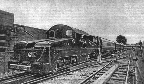
The locomotives are eight-wheeled, consisting of two four-wheeled trucks joined together and surmounted with a cab. The distance between the wheel centers of each truck is five feet eight inches. The motors are gearless and mounted directly on the axle, without the cushioning support which has sometimes been the practice. The armatures are built up on brass sleeves, which are afterward forced on to the car axle. The weight of the armatures and commutators, without the axles, is 3,000 pounds, and the complete motor weighs 12,000 pounds. They are four-pole machines, and their rating is 117 horse-power. The controllers connect the motors two in series, two in parallel to start and then throw all four in parallel for full speed. Westinghouse air brakes are used.
 |
| Fig. 3. Central London Underground Railway. Electric Third Rail. |
The track and third rails are of the section shown in Figs. 3 and 4, and look rather peculiar to American eyes. The track rails weigh 100 pounds per yard and the third rails 85 pounds. The third rail is midway between the track rails.
 |
| Fig. 4. Central London Underground Railway. Track Rails. |
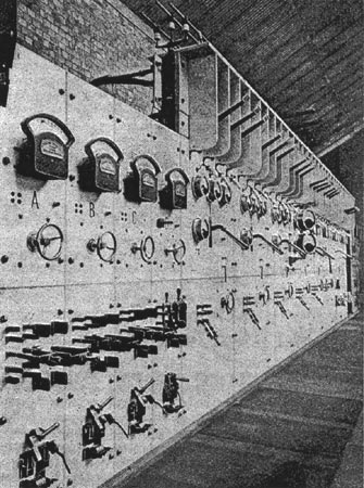
The power station corresponds closely with the latest and best American practice. Hunt conveyors, driven by electric motors, supply coal to Vicars mechanical stokers under 16 Babcock & Wilcox water-tube boilers, each capable of evaporating 12,000 pounds of water per hour at 160 pounds per square inch. The engines are run condensing with the aid of a Barnard-Wheeler water-cooling tower, similar to that used on the South Side elevated railroad of Chicago. Six compound condensing Allis-Corliss engines are direct-connected to 800-kilowatt, three-phase, revolving-field alternators, giving current at 25 cycles, 5,000 volts. The electrical apparatus was all furnished by the General Electric company, through the British Thomson-Houston company. The exciters are four, of 50-kilowatt capacity and direct-connected to vertical engines. The 5,000-volt supply from the alternators is sent out to three sub-stations, where it is transformed down and delivered to rotary converters, which give direct current to the third rails. Fig. 5 shows the main switchboard, which is provided with high-tension Parshall switches, which make a long break, both on the front and back of the board, and are separated by marble partitions, as seen. The method of running the high-tension buses along the top of the board can also be seen. All the alternating-current ammeters and voltmeters are Hartmann & Braun hot-wire instruments. All the electrical and steam-engineering features are the design of H. F. Parshall, consulting engineer of, the Central London railway, who has been identified with the most important electric-railway engineering in England the last few years, as he was in this country in former years.
For the illustrations and information in the fore-going credit is due the London Electrical Review.
| |||
| Fig. 5. Central London Underground Railway. Main Switchboard. |