[Trade Journal]
Publication: Western Electrician
Chicago, IL, United States
vol. 29, no. 16, p. 268-269, col. 1-3,1
Electrical Growth and Improvement in
Boston.
From the annual report for 1900 of Mr. William H. Lott, commissioner of wires for the city of Boston, the following facts of general interest are taken:
The old style of roof construction is rapidly disappearing in the business section of the city, and it is seldom that a fixture is placed upon a roof except by companies operating high-potential wires. The system adopted by the Low Tension Wire association is to trunk its wires along the walls of buildings, and not cross over the roofs. This style of construction is less expensive and less objectionable to property owners. The companies also avoid the responsibility and care of the roofs. The expense of keeping roofs on which fixtures are located in repair has always been very heavy, and a burden which the companies are striving to relieve themselves of as fast as possible.
| |||
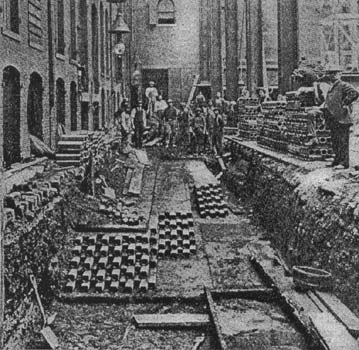
| Fig. 1. Electrical Growth in Boston. — Conduit of Edison Company. |
The result of fuse inspection has been more than satisfactory, it seldom being found that an installation has been made without the line being suitably protected. This is a safeguard, and a great improvement over the conditions at the time the Wire Department was created, as inspection at that time showed that the absence of suitable protection devices was the rule rather than the exception.
During the past year a marked improvement has been made in the pole-line construction, fewer accidents having occurred to workmen required to handle the wires than in any previous year since the Wire Department was created.
The city has been divided into districts, and an inspector assigned to and held responsible for the conditions of the wires in each district. This proves to have been a great help in keeping the construction in good condition, as the inspectors early familiarize themselves with the condition of the streets. The inspectors are required to go over their entire district once in four or five weeks, and consequently they are quick to notice any changes that may have been made in the wiring since their previous inspection. Any defects noted are reported and the interested parties at once notified from this office of the defect, which notice in most cases receives prompt attention, the Wire Department being notified of the action taken on same, and it is found usually that repairs have been made in a satisfactory and approved manner.
Every effort is being made to separate the low from the high-potential wires so as to reduce the danger to linemen who are obliged, owing to the nature of their work, to come in contact with the same. In order to successfully carry this out it has been necessary to erect two lines of poles, one on each side of some of the streets; when this cannot be done, a separation is required, when it is possible, of 40 inches. I will add that the officials of the leading companies, realizing the importance of this step have rendered this department every assistance possible to carry this out to a successful conclusion.
A survey is being made to determine the exact location of every pole in the limits of the city used for the support of telegraph, telephone, fire-alarm, police, electric-light and other wires. This is a difficult task, and is one which has never before been attempted, to my knowledge. It is estimated that there are about 20,000 poles standing in the streets at the present time, not including the poles of the Boston Elevated Railway company, used for the support of trolley wires. Of the location of these poles there is no correct record. This work is being carefully done and a watchful care kept of removals, renewals, changes, etc., and a record of the same kept on atlases and books provided for this purpose, so that it will be possible at a moment's notice to arrive the ownership, location and condition of any pole of which information is desired; a thing very necessary on account of the growing number of inquiries, which are made almost daily.
| |||
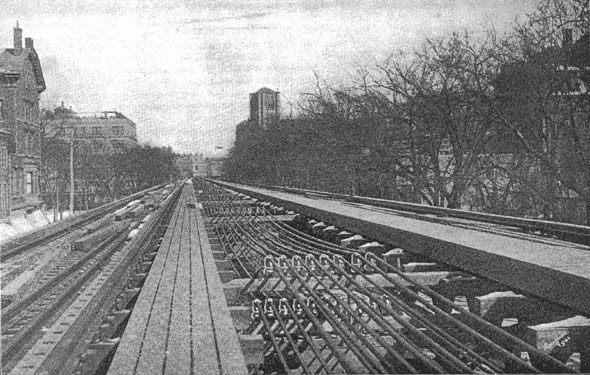
| Fig. 2. Electrical Growth in Boston. — View Showing Cables on Elevated Structure. |
Iron lamp-posts, which have for many years been in use, to support arc lights for street lighting, are being replaced by approved wooden posts. This style of post is being used by the Brook-line Gas Light company and the Charlestown Gas and Electric company, in their respective districts,, so that it is reasonable to expect that in a short time none of the old pattern will be in use in any part of the city. The Boston Electric Light company was the first to use the new-pattern posts, and the absence of accidents to linemen and trimmers in its employ shows it to have been a wise move.
In the streets in which the elevated structure has been built by the Boston Elevated Railway company the structure has been utilized for the carrying of heavy lines of feeder wires required for the operation of the surface-car lines. The feeder wires have been placed on the structure with a view of securing the safest construction possible in relation to the structure and such other wires and fixtures as are used for the operation of both elevated and surface cars, i. e., trolley wires, third rails and third-rail feeders. The feeder wires are mostly 1,000,000 circular mils in size, and their insulation consists of a covering of three layers of braiding, filled with insulating compound.
Owing to the changing type of construction used for the elevated structure, two distinct methods of supporting the wires had to be used.
Where plate cross-girders were used three-inch holes were drilled on six centers in the middle of the cross-girder, and so situated that the wires would come in the space between the two pair of longitudinal girders. Thus, while at a considerable inconvenience for stringing, the wires would be placed upon the structure where they would be the least obtrusive, and so contribute to the general neatness of the whole construction.
Where the arched cross-girder construction obtained, the only available space for carrying such a heavy line of feeders was immediately over the middle of the arch and between two pairs of longitudinal girders for the tracks, but at a level slightly higher than the tops of these girders.
In the plate-girder construction the feeders are threaded through the three-inch holes, the girders averaging nearly 50 feet apart. At each girder where the wires pass through, and outside of the space occupied by the holes for the feeders, on both sides of the plate-girder, vertical pieces of hard pine are bolted securely to the plate. Then, to these vertical wood pieces, are fastened three-inch by three-inch cross-arms, placed in proper relation to the horizontal row of holes. These cross-arms alternate on each side of the cross-girders with each successive horizontal row of holes, this being necessary to give working room between the cross-arms for the proper placing of the insulating supports, it being remembered that the, centers of holes are only six inches apart.
The wood cross-arms are used to give an electrically safer support for the insulator which carries the wires, and at the same time to give a support which will carry the wire through the three-inch holes in the plate girder, clear and independent of the sides of the hole.
A supporting porcelain insulator is screwed fast to the top of the cross-arm and so placed that it holds the wire in the center of the hole in the girder, thus precluding the danger of the wire coming in contact with the ironwork, or sides of the hole. As an additional safeguard, a hardwood sleeve, split and about five inches in length and treated with an insulating compound, is fastened about the feeder wire at the point where the wire passes through the three-inch hole, thus avoiding any chance for abrasion to the insulation of the wire, even should any mishap occur to the main support.
To avoid putting any other but a vertical strain upon the insulating supports just described, in order to hold the wire tight and keep slack out of the sections as much as possible, dependence must be had upon the method of anchoring the wire at the ends and at long intervals in the line.
To meet the severe strain which a 1,000,000-circular-mil wire would necessarily put upon any kind of insulating anchor appliance, an entirely safe insulator, and strong anchor appliance is made of two properly shaped blocks of lignum-vitae wood, held in tandem with iron straps, which are bolted together through the centers of the wood. The feeder wire is wound around in the groove of one of the lignum-vitae blocks and there fastened, and in a similar manner a heavy galvanized-iron guy wire, or specially placed wrought-iron clamp is placed in the groove of the other block, and this connected with a clamp or other fixture, held securely to the cross-girder.
A double insulation of the very highest strength is thus secured.
The constructions used for the support of the wires on the arched cross-girder of the structure is, in effect, and it might be said, in fact, the same as is in common practice on heavy pole-line feeder construction, i. e., wood cross-arms, locust pins and petticoated-glass insulators of the '"Jumbo" type, the only difference being in the method of holding the cross-arms in place.
Although the district prescribed for the removal of overhead wires during the year 1900 was much smaller than for any previous year, yet there was more underground work done than ever before in one year.
The falling off in cables is due to the fact that the Boston Electric Light company during the year 1899 connected up their L street station, drawing cable amounting to over 1,200,000 feet.
While the accumulation of illuminating and other explosive gases cannot be wholly prevented, yet with the present system of inspection, and the prompt action of the gas company in seeking for and stopping the leaks when notified of their existence, through the presence of gas in the manholes, there was but one explosion during the past year. There have been 18 such explosions since the organization of the Wire Department, the greatest number in any one year being six, and one year there was none.
From the ducts surrounded by concrete, and the conductors contained therein, little trouble need be apprehended, but where the iron ducts for service connections and the solid-tube system are laid in the earth, without the protection of concrete, they are exposed to and receive injuries that often lead to results that may at times prove serious.
Great care is exercised by this department in the supervision of underground electrical construction to provide ample separation between the ducts and gas, water and other pipes that are met with underground, and no difficulty is experienced in doing so; but as this department can exercise no control over the operations of the employes of other departments and private contractors engaged in excavating the streets, injury to this class of conduits and the conductors they contain, and contact between them and other conducting material, are too frequent for the public good.
The solid-tube system depends very largely on the earth for its stability and reliability, and the earth should not be removed from under any portion of it if it can be avoided; but as it cannot be, the greatest care should be taken to give it proper support and to maintain its alignment; but this is not always done. The tubes of this system are 20 feet in length, and are connected together by cast-iron junction boxes that are halved longitudinally and held together by screws; they contain flexible conductors that join those in each consecutive tube together and are filled with an insulating compound. As the tubes are not screwed into these boxes, should the earth be removed from under them for any considerable distance each side of them, unless rigidly supported in some way the tubes pull out, the conductors are severed or are brought in contact with the tube or box, turning them into a conductor, and should the tube at any point be in contact with gas or water pipes, current would be, and in a great many cases has been carried into buildings, causing more or less damage. Should the service ducts containing high-potential wires be brought in contact with the water or gas pipes in like manner, and should the insulation of the wires fail, in addition to the danger from fire, there would be that of injury to persons as well.
| |||
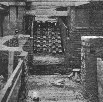
| Fig. 3. Electrical Growth in Boston. — Conduit of Massachusetts Telephone Company. |
Since the organization of this department there have been 12 cases where a dangerous amount of current has been carried into buildings over the pipes supplying them with illuminating gas, four of which occurred during the year 1900. There have been two cases where holes have been burned through the gas mains in the street where they were in contact with the tubes of the Edison system. There have been no cases reported where the electrical ducts and tubes have been found in contact with water pipes, which is due, no doubt, to the fact that the latter are laid below the frost line, while gas pipes and electrical conduits and ducts are not, except in rare cases when it is necessary to avoid obstructions, so the danger resulting from contact between water pipes and electrical conduits is very small.
The summary of the work of all the companies, both high and low-tension, for the year, is as follows:
167,766 feet of conduit completed, 851,104 feet of duct laid; 784,488 feet of cable drawn in ducts; 1,035 service connections made; 582 manholes built; 24 distribution boxes set.
 |
Referring to the accompanying illustrations. Fig. 1 shows a conduit in process of construction for the Edison Electric Illuminating company, composed of 120 three-inch vitrified-clay ducts. This conduit is laid in the private-way approaching the new station of this company on Atlantic avenue, opposite Pearl street. Fig. 3 shows a conduit in process of construction for the Massachusetts Telephone and Telegraph company on Franklin street, and composed of 72 ducts of three-inch vitrified clay. The manhole, which is partially built, is in front of the building occupied by the company at No. 185 Franklin street. Fig. 2 gives a fair idea of the manner of stringing the feed and return cables of the Boston Elevated Railway company on its overhead structure, showing the cross-pieces between the tracks and glass insulators supporting the wires.


