[Trade Journal]
Publication: Western Electrician
Chicago, IL, United States
vol. 29, no. 2, p. 18-20, col. 2-3; 1-3, 1
Construction and Protection of Aerial Systems.
By K. B. THORNTON.
In this country the majority of transmission and distribution systems arc of overhead construction, and are likely to remain so for many a long day. As these systems are exposed to all kinds of weather it is a matter of great importance to those who arc operating the same that they be constructed and protected in the best possible manner. Aerial lines arc constructed by placing wooden or iron poles in the ground generally at distances varying from 105 to 120 feet apart in cities, and from 90 to 100 feet apart for high-voltage transmission lines in the country.
For wooden poles. cedar wood, owing to its lasting qualities, is generally used up to lengths of 50 or 55 feet; beyond this length they are hard to get of suitable proportions. the tops being often too small and the butts too large, and the price prohibitive. Apart from this cedar is also too brittle a wood to use for high lines. Spruce and pine poles are therefore used where lengths over 55 feet are required. chestnut and other desirable woods not being obtainable in this country. As it is daily becoming harder to get long poles it is often necessary to resort to splicing poles to get the proper lengths.
Good cedar poles will last for twenty years and more without showing any signs of rotting. but red pine poles will generally rot at the butt in cities in less than 10 years. and spruce poles often show signs of rotting in four or five years. depending very however, on the nature of the ground in which the pole is located.
With a view to increasing the life of spruce and nine poles it is customary when placing them to coat the butts with a heavy coating of tar. The length of poles is governed by the conditions of locations. They are usually from 40 to 65 feet. and to clear high buildings from 75 to 80 feet. Experience has shown that it is advisable to keep the lengths of the poles as short as possible. as they are less exposed to the weather, and it is generally a hard matter in cities to guy them.
Throughout residential and suburban districts and for transmission lines through the country the usual length for poles is 40 feet. The following are some of the essential features of a pole contract:
Poles to be of good, sound. well shaped line cedar wood. not less than seven inches in diameter at the small end.
Poles to be cut square at both ends and the bark stripped off clear from the top to within six feet from the butt, and all knots to be neatly trimmed off; no pole will be accepted with two curves in it.
Poles will be inspected and branded at point of shipment, the inspector haying the power to reject any pole that he may consider to be unsatisfactory.
Shaving Poles.Poles when unloaded at the pole yard arc inspected and shaved, the cost of shaving averaging about three-quarter cent per foot.
Setting Poles.In regard to the setting of poles no regular role can be given for the depth which they should he set in the ground; usually it is from five to seven feet. depending on the height, location and the condition of the ground in which they are located.
The following are the usual depths of setting in good ground:
Height of Pole Depth of Setting.
35 to 45 ft. 5 ft.
50 to 55 ft. 6 ft.
60 to 80 ft. 7 ft.
In marshy or ''made'' ground it is often necessary to concrete the butts of poles, using a mixture com-posed of one part of cement, three parts of sand and five parts of broken stone.
Up to a height of 45 feet poles are Set with pike poles and a ''dead man," and over that height with derrick. The number of men being as follows:
Height of Pole. No. of men required.
30 ft. 6 with pike poles.
40 ft. 7 with pike poles.
60 ft. 10 with derrick.
70 ft. 15 with derrick.
80 ft. 15 with derrick.
Should the poles be wet one or two additional men may be required on account of the extra weight. The gains are cut while the pole is on the ground and also when used in cities the holes drilled for spikes.
When a pole is once set the earth is well tamped round the butt: this is especially necessary in the early spring when the frost is not quite out of the ground, and if not properly attended to. the poles will get out of line in a very short time.
Spikes are of square wrought iron, nine inches by nine-sixteenths inch, two men being able to drive about Soo per day of ten hours, once the holes are bored.
Cross-arms arc usually of red or yellow pine and vary in length for ordinary city service from two feet six inches for a two-pin arm, about eight feet for a six-pin arm, and have a sectional area of three feet four inches by four feet four inches for all ordinary work: for transmission lines the dimensions will vary front the above depending on the nature of the transmission service.
Cross-arms are rounded or chamfered on the top side to prevent water gathering and lag screwed to the poles with seven-inch by one-half inch lag screws. Some prefer to fasten the cross-arm with bolts passing through the poles. but our experience has been that it is easier to replace cross-arms that have been lag screwed than those which have been bolted, as the bolts generally rust, making it necessary to use a drift to drive them out.
Braces.All four and six-pin arms should be braced with flat iron braces not less than one and one-fourth inch by 27 inches. bolted to the cross arm by four-inch by three-eighths-inch machine bolts at one end and either lag-screwed to the pole with a four-inch by three-eighths inch lag screw, or bolted to the next cross arm underneath. On important transmission lines with long and heavy cross arms, where very strong work is required, braces of angle-iron in one piece are sometimes used.
A brace composed of one piece has some distinct advantages. For instance, some time ago one of the wires on a high-voltage transmission line slipped off the insulator onto the cross-arm, and the current to ground through the pole burned the cross-arm entirely off the pole, leaving the two outside ends of the arm supported by the brace, permitting the service to remain uninterrupted until such time as the line could lie conveniently shut down.
Pins are fitted in holes drilled in the cross-arms about 15 inches apart and 22 inches between the center two pins, and secured by a wire nail driven through the cross-arm. After considerable experience with oak pins they have been abandoned in favor of one-and-one-half-inch locust-wood pins, it being found that oak pins after five or six years were inclined to rot and break off at the shoulder when subjected to any great strain. Where great strength is required at corner poles or for dead-ending, it is advisable to use solid iron pins.
On long straight runs it is advisable to set the cross-arms in such a way that they alternately face each other on adjacent poles and arc back to back on the next two poles: in this way, should a stretch cut down or a pole break, there is less danger of the cross-arms being wrenched off than if they were all set in the one direction.
At all long stretches, corners. and for dead-ending. cross-arms should be doubled. with a spacing block at either end of same and fastened at the ends by bolts run through the spacing blocks.
Insulators.For regular line voltages of 2,000 to 3,000 volts. the ordinary deep-grooved. double-petticoat glass insulators are used: for higher voltages it is necessary to use specially prepared triple-petticoat it is better to use a lap joint as it runs over the cross arms easier when the wire is being strung.
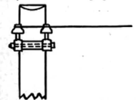 |
| Fig. 1. Construction and Protection of Aerial Systems |
Dead-ending.Lines are generally dead-ended or double cross-arms, the wire being twisted round the insulators and then back on itself, and the tie wires soldered to the line wire on the last two or three poles. (Fig. 1.) For high-voltage lines, a dead-ending arrangement. consisting of a series of globe strain insulators is sometimes used, the line being fastened to one end of a string of strain insulators, the other end of which is bolted through the cross-arm as shown in Fig. 2. This system of dead-ending is not altogether satisfactory, as the insulation of the strain insulators deteriorates and breaks down. Fig. 3 shows another method for dead-ending high-voltage lines, which has proved to be very satisfactory. although more expensive than that shown in Fig. 1. With this arrangement the wire is tied round two insulators supported on a special iron bracket, which is bolted through the cross-arm, the center of the wire being in line with the shank of the bracket.
- Stringing Wire.Wire when strung is subjected to mechanical strains due to weight, tension, variations in temperature and additional weight in winter due to ice, and when stringing wire in our Canadian climate, special allowance must be made for variations in temperature. Dynamometers arc not ordinarily used to deter-mine the tension of the wire strung. but experience has shown what sags to allow between poles for different sizes of wire.
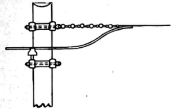 |
| Fig. 2. Construction and Protection of Aerial Systems |
The deflection of a wire supported between two points is given by the formula:
 |
Stresses.Pole lines are subjected to various stresses which have all to be provided for. These stresses are firstly, those due to the weight of the conductors and fixtures on pole. or the weight of ice on the conductors together with their weight tending to crush the pole, and secondly, those due to the lateral pressure of the wind on the pole and conductors. tending to break the pole by bending; the action of the wind also has the tendency to break the pole near the ground due to vibration. The danger due to crushing is not very great as there is always a very large factor of safety. On one of the heaviest pole lines in Montreal the factor of safety for crushing under ordinary conditions is about 400. Once during the winter, after a very heavy sleet storm, this factor was reduced to about 240, owing to the extra weight of ice on the wires. The stresses, however, which are most to be feared, are those caused by wind. The same pole line mentioned was blown down in November last during a hurricane, about 18 70-foot poles being broken. McGill Observatory reports gave the velocity of the wind at 75 miles per hour which is equivalent to a pressure of 25 rounds per square foot. This represented a total pressure on each stretch of this particular line, of 3,750 pounds, and there is no doubt if this had been applied as a constant pressure, that the poles and guys would have withstood same. However, the com-bination of the wind and the swinging of the wires evidently produced a strain in excess of the strength of the poles and guys.
Guying.All lines require lateral support in the Tape of braces or guys to withstand wind stresses, the poles themselves when loaded with wires being unable to withstand same. In the country, poles can he side braced with short wooden poles or guyed with anchor rods. but in cities this is impossible and guy wires have to be used. Galvanized iron or stranded steel is used for guy work, the stranded steel being preferable as it is much more flexible and its weight length for length considerably less. On long, heavy lines, poles in addition to being side guyed. should be guyed with crossed head guys every four or five stretches to prevent the line running back or the poles breaking, should any single pole in the line break or a stretch be cut or broken down. Where there are several cross arms on a pole the "Y" guy is most useful, and at points where circuits dead end on one side of a cross arm"Y" guys should also be used to prevent the arms being twisted out of line.
The practice of guying to trees and buildings should be avoided in all cases, for aside from making poor anchors for guys, they are subject to removal at a minute's notice from the proprietor and the company owning them is also liable for damages.
Lightning Protection.The protection of aerial lines from the effects of lightning storms, is a matter which has received considerable attention from all central-station engineers operating overhead systems. With the advent of, high-tension transmission lines. the difficulty of effectively protecting same has been greatly increased. Overhead systems may be affected in the three following ways:
(1) By direct strokes.
(2) By induced discharges.
(3) By electrostatic induction.
Fortunately for electric installations. direct strokes do not frequently occur for probably no arrester would be of much service in preventing such a discharge from doing considerable damage. Induced discharges following a lightning flash and static charges. due to surrounding atmosphere being charged. are the conditions which have to be specially provided against.
Owing to the high frequency of lightning discharges any inductance on the line offers an enormous impedence to a discharge, which fact accounts for the puncturing of transformer coils. the discharge taking the shortest and most direct path to ground.
Arresters are non-inductive resistances usually air gaps, one side being connected to the line and the ether to earth, the resistance of these gaps being low enough for the lightning to choose same for a path to ground rather than through some of the apparatus connected to the lines.
The length of the gap is governed by the working voltage of the line. the general practice of the day being to make it as small as possible without the ordinary current jumping across. However, this has the disadvantage that arresters are apt to be too sensitive and cause trouble due to dust, cobwebs and dirt accumulating, or the fusing over of the spark gaps due to repeated discharges, thereby causing a short circuit on the line or a heavy ground as the dynamo current. follows the lightning discharge across the gap.
A lightning arrester, in addition to affording a short path to ground, must also perform the duty of pa arc-breaking circuit-breaker to interrupt immediately the flow of the line current to ground and extinguish the arc which is formed.
Owing to the fact that any inductance in the line offers. considerable resistance to the passage of a lightning discharge. choke coils are sometimes introduced in series with the line, between the arresters and the central station, the combination of arresters and choke coils forming a very reliable means of protecting the apparatus in the station.
It is not a general practice to install a choke coil in conjunction with every arrester placed on the line. owing to the high cost which would be involved; however, it is a good scheme to place such a combination to protect any large and expensive apparatus connected to the circuits. These choke toils are usually constructed of flat copper strip wound on a non-conducting core the layers being insulated with mica or some other insulator.
Any self-induction in the way of coils or turns in the ground wire of an arrester must be avoided and when they are being put up, the linemen should watched, as it is a favorite trick to take up any slack in a wire by making a little coil ; any such would be nothing more or less than choke coil which would completely offset the value of the arrester, rendering it virtually useless.
The ground wire k a most important feature in the installation of a lightning arrester and there is no doubt that many failures of arresters to protect lines are due to poor ground connections. To protect a circuit effectively, arresters should be placed at the end of all lines and at points where they branch off in different directions and they should be inspected and cleaned from time to time.
Despite the many devices used on the various types of arresters to extinguish the arc formed, the line current is occasionally not broken, thereby causing a short circuit or dead ground. To avoid this fuses are sometimes placed on the ground wire of single-pole arresters and in both leads of double-pole arresters; this however, makes it specially necessary that an inspection be made after every storm so that should any fuse be blown it can be replaced before the next storm.
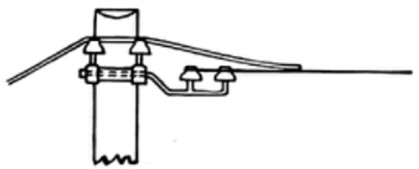 |
| Fig. 3. Construction and Protection of Aerial Systems |
Barb Wire.Owing to the somewhat uncertain action on lightning arresters barb wire has been used on transmission lines as a protection against lightning, and the results obtained have clearly demonstrated that it is a most satisfactory means of protection.
Barb wire is usually strung on pins on top of the poles and also at the ends of the top cross-arm. In some places a special two-pin cross-arm has been used above the line wires, to carry the barb wires, and in other places a single line of barb wire is strung on top of the pole. Experience has shown that it is advisable to fasten the barb wire to glass insulators un pins rather than to staple it to the pole, owing to the superior mechanical support, the insulator of course not being used for insulating purposes. Some engineers consider that the trouble caused by using barb wire offsets its value as a protective device; and for that reason its use has been abandoned in one or two instances.
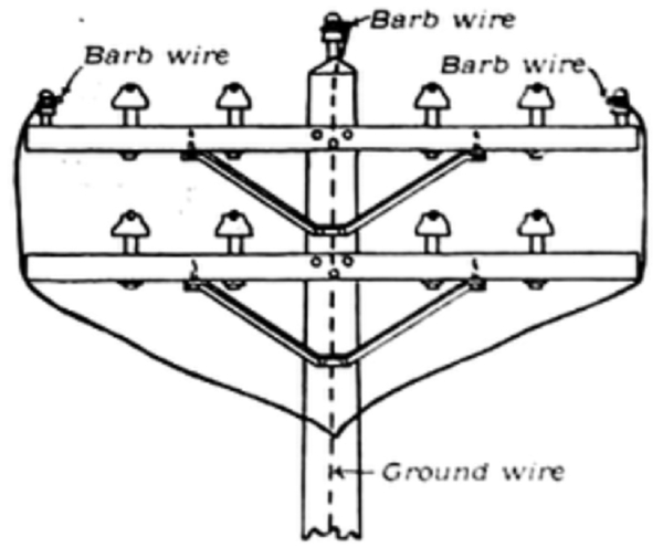 |
| Fig. 4. Construction and Protection of Aerial Systems |
A description of the methods adopted to protect the Chambly 12,000-volt transmission lines from lightning may be of interest, as the results obtained on the two lines have been eminently satisfactory.
Two duplicate lines are run front Chambly to Montreal, the total distance being about 17 miles for each line, of which 14-1/2 miles are aerial and 2-1/2 miles underground cables. The underground cable is divided up in three sections. the first section being about a mile and a half from the powerhouse, the second about 15 miles front the powerhouse. and the third at the Montreal end.
The country through which the lines pass is very flat and marshy towards the Montreal end. Three lines of barb wire on glass insulators are run on each pole line as shown in Fig. 4. two lines being run on the ends of the top cross-arm about 15 inches from the line wire and the third on a pin on top of the pole.
The barb wire is composed of two twisted No. 12 B. W. G. galvanized-iron wires with one four-point barb every five inches and is connected at each pole by means of a soldered joint to the ground wire. This ground wire is stapled down the face of the pole and is twisted several times around the butt, after running through an iron pipe about eight feet long, which projects above the level of the ground preventing the wire from being cut or broken as well as affording an additional ground.
The ground wire and pipe were stapled on the pole when the poles were being erected.
As the poles on the transmission lines are set 90 feet apart the barb-wire lines are grounded about 58 times per mile; this frequent grounding being one of the most important points in the protection.
It was the intention before putting the lines into, use to place lightning arresters in addition to the barb wire. but as they were not available in time the lines were put into operation without them.
Our experience with the first series of storms showed that well-grounded barb wire was a very effective protection, and the lines were therefore operated under these conditions for one entire summer.
Recently arresters of the air-gap type. have been installed at the powerhouse at Richelieu as additional protection.
During one particularly severe storm the local distribution lines in Montreal and Chambly, which were not protected by barb wire, were considerably affected, while no effects were felt on the transmission lines at all. although trees were struck in the immediate neighborhood.
It was at first thought that the barb wire would rust and break down very quickly, but after two years' operation an inspection shows that it is in a very good condition, and as yet there has never been a single case of it breaking.
