[Trade Journal]
Publication: Western Electrician
Chicago, IL, United States
vol. 29, no. 14, p. 218-219, col. 1-3
Chicago-Joliet Electric Railway.
Chicago is the center of a gradually increasing network of suburban electric-railway lines. One of the most important of the roads extending west-ward is the one connecting Joliet with the larger city. This line, which has just been opened for traffic, is operated by the Chicago and Joliet Electric Railway company, and runs from Joliet in a north-easterly direction through the Desplaines valley to the southwestern limits of Chicago at Archer and Forty-eighth avenues, paralleling for much of this distance-30 miles-the Chicago Drainage channel and several steam-railroad lines.
The Chicago and Joliet Electric Railway company is a consolidation of the Chicago and Joliet Rapid Transit company, the Chicago and Desplaines Valley Electric Railway company and the Desplaines Valley Electric Railway company, all of these companies originally securing franchises over which the present road operates. The consolidation was made by the American Railways company of Philadelphia, which now controls the road.
| |||
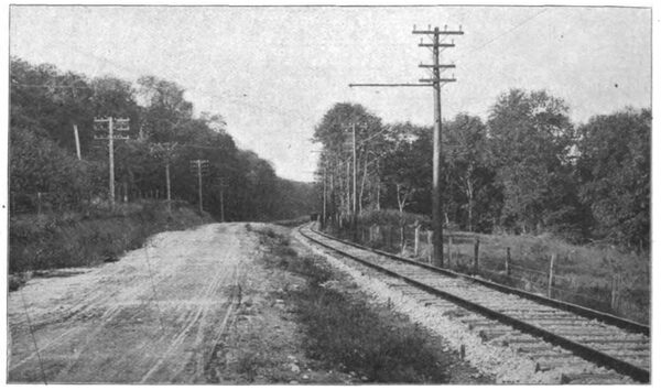
| Fig. 1. Chicago-Joliet Electric Railway. — View Near Willow Springs. |
The formal opening of the line occurred on Wednesday, September 25th, and was the occasion of a somewhat elaborate celebration. A party of city officials and invited guests from Joliet and the neighboring towns started from the southern and western terminus of the road in the morning and meta similar delegation from Chicago at the Chicago terminus. The entire party, occupying eight large cars, then proceeded over the line, making stops at points of interest and arriving at Joliet in the middle of the afternoon . The railway company had fastened small flags on every pole along the route and many of the residents had decorated their homes in honor of the opening of the line. At Joliet the party was taken to Ingalls Park, where an elaborate banquet was served to the 400 or more guests, and appropriate remarks were made by Mayor Barr and others of Joliet, Deputy City Controller Frost and Clayton E. Crafts of Chicago, Manager Fisher and others. On the following day, September 26th, the regular schedule of car operation was put in force, and the road was placed in full operation.
For the greater portion of its 30-mile route the Chicago and Joliet electric railway follows a public highway and in places passes through very pretty stretches of country. Starting at the city limits of Chicago the route lies along the old Archer road, and the first towns reached are Lyons and Summit. At the latter place is located one of the company's sub-stations. Bethania, Mount Forest and Willow Springs are then passed through and about a mile further west the cars pass along a beautiful wooded highway. A view of the track at this section, looking west, is given in Fig. 1. Up to this point the road has a single track, with frequent turnouts. The picture gives a typical view of the one-track, bracket, side-pole construction used from this point north.
| |||
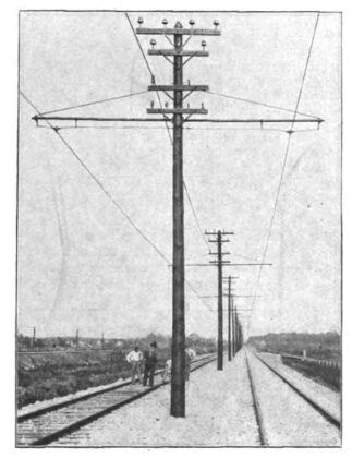
| Fig. 2. Chicago-Joliet Electric Railway. — Center-Pole Construction Near Sag Bridge. |
At the next station, Sag Bridge, begins a long two-track section that runs across a level piece of ground. The center-pole and bracket construction that is used for this piece of the track is well illustrated in Fig. 2, which shows this section, looking east. The steam-railroad track at the left of the picture is that of the Chicago and Alton railroad, which the electric line parallels for nearly its entire length. Passing on from Sag Bridge, the road touches Hastings and then passes through Lemont, where a second sub-station is located. From Lemont to Joliet, through the towns of Romeo and Lockport, the road is double-tracked, a side-pole, span-wire construction being used.
The track foundation is, or will be, rock-ballasted throughout, and in every respect the roadbed is constructed in accordance with standard steam-railroad practice. In the two illustrations above referred to, the rock ballasting shows plainly. Steel rails, weighing 70 pounds to the yard, are used. As the line passes through some of the largest stone quarries in the state, the necessary material for the roadbed was easily and cheaply obtained.
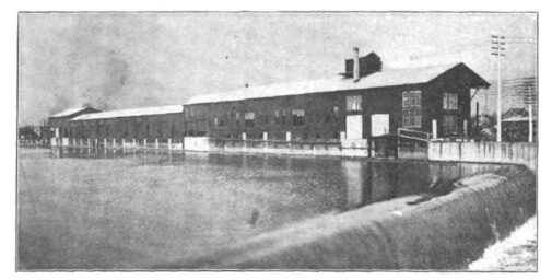
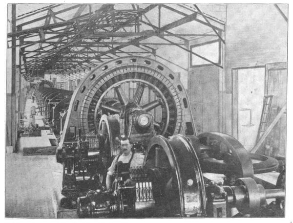
Electric power for the operation of the railway is obtained from the waterpower plant of the Economy Light and Power company at Joliet. This company has built a power house on concrete foundations at one side of, and parallel with, the Desplaines River, which at this point has its power increased by the waters of the Chicago Drainage Canal and the old Illinois and Michigan Canal. In the Western Electrician of September 22, 1900, a detailed account of the power-development plans of the Economy company was given, showing the progress made up to that time. The ultimate plan of this company contemplates a waterwheel plant consisting of 40 turbines, the large number being made necessary on account of the low head of water, which is only 15 feet at its maximum at this point. At present the power house, as shown in Fig. 3 extends over only 22 of the waterwheel bays. The new portion of the plant consists of 12 66-inch turbines, connected in sets of six each, each set driving a750-kilowatt alternator, and two 48-inch wheels, each separately connected to a 75-kilowatt, 125-volt, direct current exciter. A view of the two alternators, one at either end of the row of waterwheel gearings, is shown in Fig. 4, the exciters being seen in the foreground. The two 750-kilowatt alternators are of the revolving-field type and generate a 60-cycle three-phase current at 2,300 volts. They were built by the General Electric company, while the water-wheels were supplied by the S. Morgan Smith company.
| |||
| Fig. 3. Power House of Economy Company at Joliet. |
CHICAGO-JOLIET ELECTRIC RAILWAY.
| |||
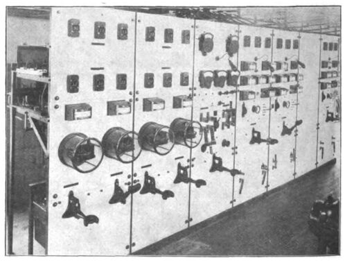
| Fig. 5. Main Switchboard of Economy Company's Plant. |
CHICAGO-JOLIET ELECTRIC RAILWAY.
The current is carried to the seven-panel switch-board illustrated in Fig. 5 and from there distributed. The Chicago and Joliet Electric Railway company has contracted for all of its power with the Economy company, and at present uses nearly the full capacity of one of the 750-kilowatt generators. The first panel on the left of the board is used as a feeder panel for the railway circuit, which is carried to a separate transforming room at the extreme north end of the building. The second panel on the switchboard is used for other power circuits, while the third panel controls the exciters and indicates the total load carried by the plant. Panels four and five control the two 750-kilowatt generators; the next panel is blank, while the last one is connected with a smaller alternator at the south end of the power house. The switch-board is of white marble and is equipped with oil switches and all the necessary instruments, fuses, etc., for an alternating-current board of this nature.
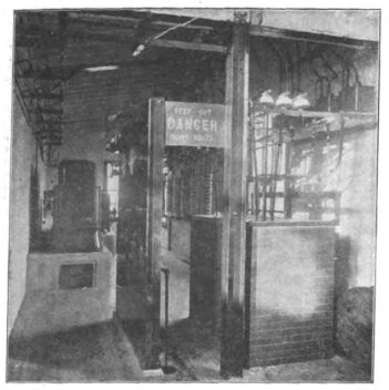
The transformer plant of the railway company, which is shown in Fig. 6, consists of four 200-kilowatt, air-blast transformers, a two-panel switchboard, the necessary lightning arresters, oil switches, etc. The 2,300-volt current from the station switchboard is received on one panel of the railway company's board, which is provided with an ammeter and an indicating and an induction wattmeter. It is then carried to three of the air-blast transformers, one being held in reserve, which raise the voltage to the line potential of 15,000 volts. This high-potential current is then passed through the other panel of the switchboard, which is provided with an ammeter, two time-limit relays and signal lamps and two switches, and out to the line on two three-phase, 60-cycle circuits.
At Joliet the railway company has a sub-station and one each at Lemont and Summit. The Joliet sub-station receives current at 2,300 volts direct from the Economy company's power service, while the other stations operate on the high-potential transmission circuits. None of the station buildings is completed, although the electrical machinery is installed and in operation. As the equipment is very similar at all three plants, a description of the installation at Lemont will suffice for all.
| |||
| Fig. 6.Chicago Joliet Electric Railway. — Transformer Room at Joliet. |
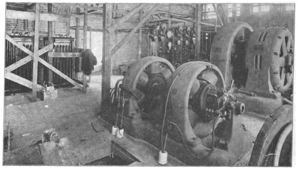
The three-phase circuit at this point has a potential of about 14,000 volts and it is received by three110-kilowatt oil transformers, which step down the voltage to 575 volts. The rotary-converter outfit consists of a 360-horsepower induction motor, taking 340 amperes at 550 volts, and a direct-current multi-polar generator, mounted on the same shaft. This machine has a speed of 514 revolutions a minute and delivers a direct current of 417 amperes at 550 to 600 volts to the railway feeders. A storage-battery equipment of 288 13-plate cells, furnished by the Electric Storage Battery company, floats on the system and has a regulating discharge capacity for one hour of 480 amperes. A 464-horsepower motor-generator is used as a booster or compensator. In Fig. 7 is given a view of the generator room of the sub-station at Lemont. The rotary converter and compensator are seen at the right and two of the transformers at the left. On account of the in-completed state of the building when the road was started it was necessary to put a temporary roof over this room. In the center of the picture at the back is shown the switchboard for the sub-station. This board contains the necessary panels for the rotary-converter, feeders, storage battery, etc., 10 panels in all.
| |||
| Fig. 7. Chicago-Joliet Electric Railway. — Sub-Station Equipment at Lemont. |
A similar sub-station equipment is located at Summit, where the transmission-line potential is about 13,000 volts. At Joliet the transforming and converting installation is similar to that of the other two stations, except that the rotary converters operate directly on the 2,300-volt circuit of the Economy company's service and that the storage-battery plant has 288 cells of 17 plates each, with a rated discharge capacity of 640 amperes for one hour. The rotary-converter, booster, transformer and switchboard equipment for the different stations was furnished by the General Electric company.
The transmission line is of aluminum wire and consists of six wires, equivalent in size to No. 4 copper, from Joliet to Lemont (12 miles), and six wires, equivalent to No. 6 copper, from Lemont to Summit (13 miles). Aluminum feeders are used each way from each station, the size being 648,000 circular mils, equivalent to a 400,000-circular-mil copper cable. The high-potential wires are bare and are carried on brown-porcelain, triple-petticoated insulators. The six wires are carried on the two top cross-arms, the three wires of each circuit being arranged as at the corners of an equilateral triangle, the poles dividing the two circuits. The wires are not transposed or spiraled. Feeder wires are carried on the third cross-arm and are bare except where they pass through the towns en route. The company has a telephone service with metallic-circuit connecting the sub-stations, office in Joliet, powerhouse and points on the line. The telephone wires are carried on the lowest arms of the pole line and are transposed every fourth pole. The instruments were furnished by the Sun Electric Manufacturing company of Philadelphia. In Figs. 1 and 2 the arrangement of the different wires on the poles is plainly shown.
| |||
| Fig. 4. Chicago-Joliet Electric Railway. — Interior of Joliet Power House Showing Alternators and Exciters. |
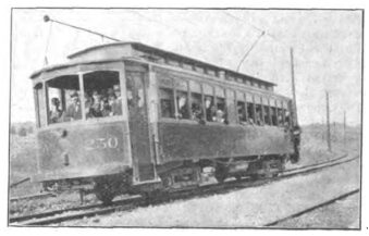
The rolling stock of the road includes eight new Brill cars of the type illustrated in Fig. 8. They are 48 feet in length and seat 52 people. They are provided with double-truck equipments, each car having four 50-horsepower General Electric motors. The cars have a rated speed of 40 miles an hour, but can be speeded up to about 50 miles an hour. Some of the cars have smoking compartments an some baggage and express rooms. All are provided with toilet rooms. Electric signal push-buttons are provided at each seat. Inclosed vestibules, with folding doors and gates, are placed at each end of the cars. Each car has two trolley poles with adjustable holders. Christensen air brakes and an air whistle form part of the equipment.
The cars are now being operated on an hourly schedule, two hours being allowed to make a runover the line in each direction. After the road is placed in full operation it is expected that a faster schedule will be put in force, and with satisfactory transfer connections at Chicago, it is believed that passengers can be carried from Joliet to the court-house in Chicago in about two hours. At present connection is made with the Archer avenue line of the Chicago City Railway company. A plan has been proposed to build a spur from the main line near Summit to Riverside, where connection will be had with the Suburban railway now making connection with the Lake Street and Metropolitan West Side elevated roads.
| |||
| Fig. 8. Chicago-Joliet Electric Railway. — Car on Curve Near Sag Bridge. |
The Chicago and Joliet electric railway parallels for the greater part of its route the tracks of the Santa Fe and Chicago and Alton roads and also enters into competition with the Rock Island for suburban traffic. It is expected that the electric line will secure a good deal of express and package-freight business and also considerable through-passenger business. The regular fare on the steam railroads for one ride from Joliet to Chicago is $1.06, while the electric road has adopted a rate of 35 cents between the two cities.
The officers of the Chicago and Joliet Electric Railway company comprise the following-named gentlemen: President, S. G. De Coursey; vice-president, William F. Harrity; general manager, H. J. Crowley; secretary and treasurer, C. L. S. Tingley; chief engineer, A. S. Kibbe, all of Philadelphia; manager, F. E. Fisher, and electrician J. R. Blackhall of Joliet, Ill.

