[Trade Journal]
Publication: Electric Power Plants
New York, NY, United States
p. 252-255, col. 1
THE CHATTANOOGA & TENNESSEE RIVER POWER COMPANY.
GENERAL.
The generating plant of the Chattanooga and Tennessee River Power Company is a water power station, located on the Tennessee River, at Hales Bar, about 33 miles below Chattanooga. The dam is designed for the double purpose of improving the navigation of the river and furnishing water power for the generation of electric energy. The hydraulic and mechanical work was in charge of Mr. John Bogart, C.E., consulting engineer of the Chattanooga and Tennessee River Power Company.
The dam is about 1200 ft. long and has an average height of about 52 ft. At the west end of the dam a lock, having a clear width of 60 ft., is provided for the convenience of navigation. The lock and dam are built of cyclopean concrete. The power station is situated at the east end of the dam. Running the full length of the dam is a passageway 2-1/2 ft. wide by 6-l/2 ft. high, connecting the power house and lock. The conductors for furnishing the electricity for operating the machinery of the lock and for lighting are carried through this passage way. Near the power house a sluiceway is provided in the dam to supply water to the lower pool, at times when none is passing over the dam or through the power house.
The power station is 66 ft. wide by 353 ft. long, and in two sections, an operating building one story high, 220 ft. long, and a switch and transformer house three stories high and 133 ft. long. The operating building consists of seven bays, each containing two turbine units, making a total of fourteen. Each unit consists of three turbines mounted on a vertical shaft with a generator at its upper end. Each generator has a capacity of 3000 kw., making a total capacity of 42,000 kw. for the station. Under ordinary stages of the river only two of the turbines will be used for each unit, the third being held in reserve and used when there is a large quantity of water flowing, but giving a reduced head due to back water in the tail race. The two lower turbine wheels are 72 in. in diameter, and the upper wheel 65 in. in diameter. The turbines run at 112-1/2 rev. per min. Each unit is capable of delivering 5250 hp. with a head of 35 ft.
·
·
| |||
| Fig. 111. Transmission Lines, Chattanooga & Tennessee River Power Co. |
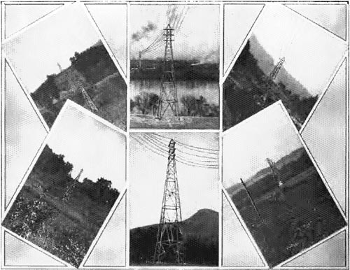
TRANSMISSION LINE.
The transmission lines leave the generating station on top of the roof at almost a right angle to the long side of the building, and are carried to the substation on 175 steel towers, exclusive of the two steel towers, one on top of the generating station and a similar tower on top of the substation.
The pins which support the large line insulators are of malleable iron, and are designed to withstand a horizontal strain of 6000 lb.
The strain insulators are furnished by the General Electric Company and the line insulators by New Lexington Company. The transmission line follows, the greater part of its route, the tracks of the N. C. and St. Louis Railroad Company, crossing them in six places, and in one instance crossing the tracks of the proposed route of the Southern Railroad Company, quite close to the border of the State of Georgia. After going in an easterly direction about two-thirds of its total length it turns sharply north and continues in that direction until it reaches a point on the river near Moccasin Bend, where it turns northeast, crossing the Tennessee River and Moccasin Bend, and crossing the Tennessee River for the second time, enters the City of Chattanooga at the foot of Henry Street.
From the foot of Henry Street the transmission line follows the easterly course parallel with Henry Street until it reaches the substation at the northwest corner of Henry and Carter streets.
There are two transmission lines carried on steel towers, each tower carrying two lines, and each line consisting of three No. 000 bare copper cables, which are used on the whole distance of 17-1/2 miles, with the exception of the two crossings over the Tennessee River, where 350.000-cir. mil bare copper cable is used.
On the top of the transmission towers a steel cable clamped to the steel structures with cast iron clamps is carried throughout the whole distance from the generating station to the substation with the exception of the two crossings over the Tennessee River. This steel cable is used as a ground wire.
The steel towers vary in height; 35-ft., 40-ft., 45-ft. and 60-ft. towers being used for ordinary spans and 150-ft. and 170-ft. towers being used for the river crossings.
Between the foot of Henry Street and the substation the transmission line crosses the N. C. and St. Louis Railroad Company tracks, and at each side of this crossing is erected a 60-ft. tower on concrete base 5 ft. high above the ground.
All the towers are erected on concrete foundations. On account of the mountainous character of the country it was not possible to have the towers located at equal distances, and, therefore, the spans vary between 200 and 700 ft., and in one instance the span being as short as 150 ft. The spans over the Tennessee River are 1400 ft. and 1500 ft. respectively. In several places it was necessary to erect angle towers, and on such the lines were dead ended.
·
·
