[Trade Journal]
Publication: American Electrician
New York, NY, United States
vol. 9, no. 8, p. 333-334, col. 1-3,1
NEW
Apparatus
AND
Appliances.
·
·
THE OGDEN (UTAH) POWER TRANSMISSION.
The power plant of the Pioneer Electric Company, of Ogden, Utah, one of the largest works of the kind yet undertaken, has in part been completed. The complete plan contemplates the utilization of the waters of the Ogden River water shed, the central features being a storage reservoir, of 2000 acres and a capacity of nearly 15,000,000 gals.; a pipe conduit, 6 ft. in diameter internally; a power house and water-wheels and electric generators, transmission lines and substations for distributing the power to different points; and an extended system of irrigation lines.
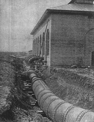
The main conduit, has, as stated above, an internal diameter of 6 ft., and a total length of 31,600 ft., of which 27,000 ft. are of wooden stave and 4600 ft. riveted steel pipe The line passes through eight tunnels, the longest being 667 ft., and over steel bridges of a total length of 560 ft., besides a timber trestle.
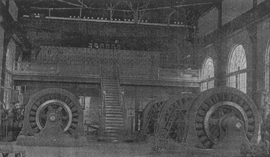
The total effective head at the power house is 446 ft. The water is delivered into two receivers, buried in the ground, one on either side of the power house (Fig. 1). The two water-wheels are 59 ins. in diameter, and have each forty-five bronze brackets cast into one solid piece; fourteen of these, when the nozzle parts are all open, receive the water at the same instant. Each wheel has a capacity of 1200 HP at 300 r. p. m.
 |
| Fig. 1. Exterior of Power House. |
The generators used in this plant are of the General Electric Company's three-phase type, with twenty-four poles and at 300 r. p. m., have an output of 750 KW at 2300 volts and a frequency of 60 cycles per second. The factory tests show that the variation in volts will be less than 5 percent, with a constant speed, should the full non-inductive load be thrown off or on.
The cable connecting each generator to its respective panel on the generator switch-board is a three-wire concentric 250,000 CM lead-covered cable, and the exciting wires are a two-wire concentric No. 4 B. & S. lead-covered cable.
The exciters used on this plant are G. E. six-pole, 500 volt machines, and will give 100 KW at 550 r. p. m. Each of these machines is ample for the entire exciting current that will be needed for the ten 750-KW alternators to be put in, and they are each direct-connected to a 135-HP Knight water wheel, similar to the 1200-HP water-wheels previously described. These exciter water-wheels are cross-connected to each receiver, so that either exciter can be operated from either receiver.
The generator switch-board consists of seven marble panels; five for the alternators, one for the exciter and one for the instrument panel.
From the generator switch-board the current is carried to the distributing board by copper bars, of which there are two sets of three, connecting the two sets of bus-bars on the generator board with the two sets of bus-bars on the primary panels of the distributing boards.
Back of this distributing switch-board are nine 250-KW air-blast step-up transformers, the lightning arresters, and the two blowers for cooling the transformers.
| |||
| Fig. 2. the Pipe Line Along the Side of the Canyon. |
Back of the distributing switch-board and on a raised platform are placed the step-up transformers. These transformers raise the potential of the current from 2300 to 16,100 volts, at which pressure it passes to the long-distance transmission lines. The transformers are connected up in sets of three, the delta connection being used on both sides. At each end of the building in the gallery are placed the two blowers, direct-connected to a 2 1/2-HP, 500-volt direct-current motor. These blowers are used in cooling the step-up transformers, and force the air up to the bottom of the transformers, around the coils and out at the top.
The transmission line is calculated to deliver about 3000 HP at the sub-station in Salt Lake City, distance about 38 miles, and consists of two circuits, making six wires of No. 1 B. & S. gauge.
The current is fed into the transmission line at the power plant at 16,100 volts and delivered to the step-down transformers at 13,800 volts. This will give an energy loss of about 10 per cent. in the line, and a potential loss of about 14 per cent. The sub-station step-down transformers deliver this current to the local distributing lines again at 2300 volts. There are at present nine 250-KW step-down transformers at the sub- station connected by the step-up transformers, and the switch-board in the substation is similar in every respect to the distributing board in the power plant gallery. The cooling apparatus here is also identical with that used in the power plant, except that the motors used are 60-cycle induction motors.
While the transmission lines are at present capable of delivering 3000 HP at the sub-station, with a 10 per cent. energy loss, if it should become necessary, the step-up transformers can deliver more than this by changing three wires on their high-pressure side, and delivering the current into the transmission lines at 27,000 volts. Thus the line capacity would be more than doubled.
The present installation of the power plant is capable of delivering 3750 KW to its lines, but ample provision has been made to increase this amount to 7500 KW by installing five more 750-KW machines, as new industries or manufactures spring up as the result of the advantages offered to them in Ogden and Salt Lake City.
The current will be used to drive factories, running electric railways from Ogden to Salt Lake City, to the Lake, to Hot Springs and to light the towns and cities in the north of the state. The surplus water in the storage reservoir will be utilized to irrigate large tracts of land in the vicinity.
| |||
| Fig. 3. Interior of Power House. |
·
·
