[Trade Journal]
Publication: American Electrician
New York, NY, United States
vol. 10, no. 9, p. 399-404, col. 1-3
THE DEVELOPMENT OF THE HYDRAULIC POWER OF THE
HUDSON RIVER AT MECHANICVILLE
The development of the power of St. Anthony's Falls on the Mississippi at Minneapolis, Minn., is followed closely by the utilization of the power of the upper waters of the Hudson River at Mechanicville, N. Y., where an undertaking of no less magnitude has, within the past few days, been completed. Five to seven thousand h.p. is available at the power house and the use of high tension current permits of its distribution over a wide territory.
As in the Mississippi, the waters of the Hudson above the present point of development have been, to some extent, employed by factories using low head turbines directly driving their machinery, but not until the undertaking just concluded was decided upon had any very serious effort been made to take advantage of the great amount of power which has run to waste for ages down the stream of the main waterway of the Empire State.
| |||
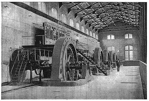
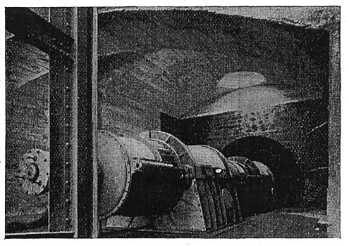
| Fig. 1. General View of Station Interior. |
Early in 1897 the attention of Mr. R. N. King, President of the Stilwell-Bierce & Smith-Vaile Company, of Dayton, Ohio, was drawn to this water power. His long experience with water powers and their development, led him speedily to recognize the possibilities which were presented. The site is but two miles from Mechanicville, eleven miles from Troy and eighteen miles from Albany, in each of which towns large quantities of power would doubtless find a market. But, most important of all, it lies only seventeen miles from Schenectady, where, covering not less than 130 acres of ground, the largest electrical works in the world are operated from an extensive steam plant, with which the electrical power from the Mechanicville cataract could readily compete.
After consultation with the chief engineers of the General Electric Company, in which the necessary assurances were given, Mr. King formed the Hudson River Power Transmission Company.
The hydraulic engineering features of the development were carried out in their entirety by Mr. A. C. Rice, Chief Engineer of the Stilwell-Bierce & Smith-Vaile Co., and it may be said that in the completed work as it stands to-day little or no departure from the plans laid down by Mr. Rice has been made. As the General Electric Company was to purchase the largest amount of power, its advice as to the electrical equipment was naturally closely followed. The result brought about by the harmonious co-operation of both hydraulic and electrical engineers is a power transmission plant in every respect strictly representative of the most modern hydraulic and electrical practice.
| |||
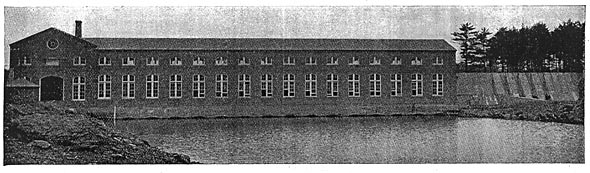
| Fig. 2. General View of Power House. |
At the point chosen for the hydraulic development the physical conditions make the location an ideal place for a dam and power house. The banks and bottom of the river are of rock, as is Bluff Island, immediately adjacent, which divides the Hudson into two channels. During the greater part of the year there is water sufficient to produce from 7000 to 10,000 h.p.
The island is about one-third of the distance across the river from the western bank, the combined width of the two channels being about 1200 ft. The western channel is used for the head and tail races.
In order to make the excavations for the power house and the main dams, heavy cofferdams were built across both streams. The work would have been completed well within the time at first specified had not an extraordinary freshet swept away part of the cofferdam, necessitating long delay. The rock and shale resulting from the excavations proved unsuitable for incorporation into concrete, and the broken rock used was brought over a special track from the neighborhood of Schenectady.
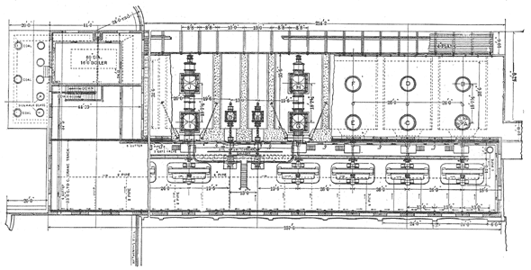 |
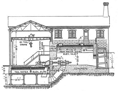
| Fig. 3. Plan of Power House. |
The power house, extends from the western bank about 215 ft. into the river and is connected with Bluff Island by a concrete dam, 26 ft. high above the bed of the river, 10 ft. wide on top and 18 ft. wide at the base. The upstream face is vertical and the downstream face is sloping. The top of this dam is at an elevation that the water will never reach; thus no provision is made to take care of falling water on the down stream side, but the dam is provided with four arch waste gates, 4 ft. wide and 6 ft. 9 ins. high, operated in the same manner as those in the main dam.
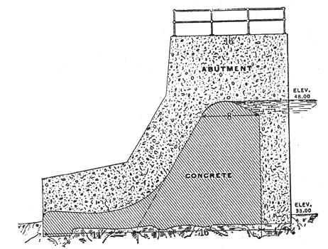
The main dam is on the eastern side of the island. It is built entirely of concrete, asindeed, is the entire construction with the exception of the upper walls of the power house. The upstream face is vertical, the downstream face is curved and provided with a horizontal apron 14 ft. wide, which throws the falling water off horizontally, and thus effectually prevents wash or scour of the toe of the dam. The dam is 16 ft. high above the river bed, 8 ft. thick immediately below the crest, 16 ft. thick through the base and 30 ft. thick through base and apron. The dam is set between massive abutments anchored to the rock sides of the river bank and island. The eastern is 20 ft. long, 26 ft. high above river bottom, 16 ft. thick at the top and 34 ft. wide at the base. The western abutment is 100 ft. long, the other dimensions being similar to those of the eastern abutment. The length of the spillway between abutments is 800 ft. In the western abutment are twelve arched waste gates of ample proportions. Each waste gate is 4 ft. wide and 6 ft. high, and is opened and closed by a heavy iron hoist operated by rack and pinion. The eastern dam is practically a solid rock wall capable of safely resisting any flood. It was severely tested in the spring of 1898, when a flood of extraordinary proportions came against it, yet, notwithstanding the fact that the dam was green, the flood in no manner injured it. To prevent any floating rubbish, ice, or logs reaching the rocks or choking the waste gates, a floating wooden boom stretches from the western end of the spillway diagonally for a distance of 400 ft. to the edge of the normal river bank, and then for a distance of 1000 ft. to the main embankment of the Mechanicville highway. It is anchored to a line of stone-filled cribs.
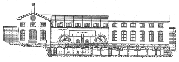 |
| Fig. 4. Side Elevation, Looking Up Stream. |
Between the west end of the power house and the Mechanicville highway a broad roadway has been built of earth and slate rock.
To avoid any possibility of water finding its way through the embankment in case of very high water a concrete core was put in the center, starting at the solid rock and finishing 2 ft. below the surface of the road. The embankment forming the roadway is 40 ft. wide on the top, 124 ft. at the base and 18 ft. high at the deepest point.
The power house lies between the west bank and the short concrete dam, nearly filling the space between the island and the west bank of the river. It is practically a continuation of the dam, and, like the main dam, is of concrete with the exception of the upper walls. Its construction is of the most substantial character, the foundations are carried down to bedrock, and the house is carried on heavy steel box-web girders resting upon steel I-beam columns. The latter are imbedded in concrete walls carrying arches which form the floor of the generator room and the floor on which the wheel flumes rest. The walls form a separate and distinct tail race 22 ft. wide for each set of turbines, from which the water may be shut out at will.
The house is divided into two parts by a thick head wall. The upstream part contains wheel chambers for seven 1000 h. p. wheels, of which five only are at present occupied. The downstream portion contains the wheel governors and the electrical apparatus. The length of the power house proper is 257 ft. 6 in.; the width of the dynamo room between head wall and south wall 34 ft., and the width of the wheel chamber portion 32 ft. 6 in. The total width of the power house is 66 ft. 6 in. At the western end an L extension runs up stream 87 ft. 5 in. long and 44 ft. 10 in. wide. This portion of the power house is of brick. A retaining wall runs down stream from the power house along the western bank a distance of 50 ft. The western stream running between the bank and the island forms the forebay, 300 ft. long. The main tail race is 205 ft. wide and joins the main stream 750 ft. below the power house.
 |
| Fig. 5 Cross-Section of Power House. |
Arched chambers are provided for seven main wheels and two exciter wheels. Each main wheel chamber is 32 ft. 6 in. long, 22 ft. wide and 17 ft. 5 in. high and is provided with two 6-ft. manholes. Each exciter wheel chamber is 32 ft. 6 in. long, 17 ft. 5 in. high and 10 ft. wide. The head wall of the chambers is 6 ft. thick, the wall on the upstream and both sides 3 ft. thick. In the head wall of each main chamber is set a heavy cast iron cover through which the the turbine shaft passes in a water-tight packing box, carrying the ring oil bearing for the shaft. The saving in space effected by the new arrangement of housing and coupling together of the turbines, patented by the Stilwell-Bierce & Smith-Vaile Co. has tended to diminish considerably the size of the power house.
A 20-ton crane from the works of Pawling & Harnishfeger, Milwaukee, runs the entire length of the dynamo room.
In front of the wheel chambers and running the entire length of the power house is a trash rack of steel bars supported on a framework of steel channel and I-beams. This rack effectually prevents the access to the wheels of any rubbish or floating material that may escape the boom.
The main wheel plant consists of ten pair of 42 in. horizontal Victor turbines of the latest type, built by the Stilwell-Bierce & Smith-Vaile Co., of Dayton, Ohio. Each main turbine consists of two pair of wheels which, at the normal speed of 114 revolutions is rated at 250 h. p. The wheel power of each set of turbines is therefore 1000 h. p. Five units are now in position; the two additional turbines will be installed shortly. The head under which the water wheels are operated is 18 ft.
The turbines for the exciters consist of three 18-in. Victor cylinder gate wheels, having, at 259 revolutions per minute, a total of 300 h.p. The quarter turns and packing boxes of these wheels are brought through the wall beneath the station switchboard.
 |
| Fig. 6. Section of Dam. |
Two draft tubes lead from each main turbine, the forward tube descending; straight into the tail race beneath the power house, the rear or upstream tube curving and flaring downward and outward. Each tube is 9 ft. 6 in. in diameter at the bottom. Two draft tubes are also allotted to each set of exciter wheels, the setting following a similar arrangement. The rear tube is 4 ft. in diameter, the forward tube 3 ft.
The speed of each set of main wheels is regulated by a Geisler electro-mechanical governor, mounted on a platform directly over the turbine shaft, and between the head wall and the generator.
| |||
| Fig. 7. View of Generator and Water Wheel Governor. |
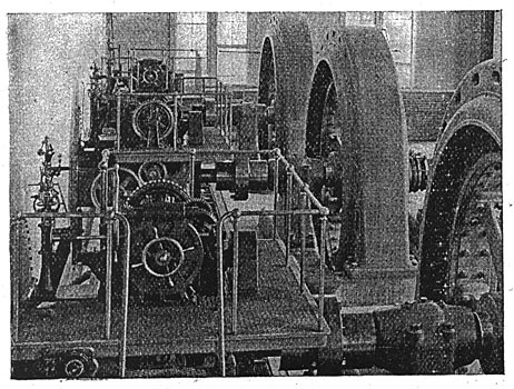
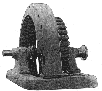
The use of electricity renders the mechanism of this governor extremely sensitive and effective, and the gates can be entirely opened or shut, should the full current be thrown on or off, in six seconds. The driving pulley is replaced by a rawhide pinion, giving a rigid connection between the governor and the wheel, and making 400 r.p.m. The speed may be increased to shut off or throw on in less than six seconds, if necessary. The Geisler governor is now in use in many of the most important electric power transmissions in this country, including those of Columbia, S. C.; Pelzer, N. C.; Lachine, Que.; West Kootenay, B. C.; Montmorency, Que.
The governors controlling the exciter wheel gates are improved "Snow" governors, which rapidly bring the speed to normal when changes are neither frequent nor heavy. They are especially adapted to the regulation of water wheels driving exciters and are provided with adjustable stops which limit the hoisting action on the gate as soon as the gate is fully open.
The dynamo room is a spacious chamber well lighted by windows on all sides. It is 255 ft. long and 34 ft. wide, 30 ft. 5 in. in the clear from floor to roof truss and 22 ft. from floor to crane. The ultimate generator capacity of the station is 7000 h.p. in seven generators each of 750 k.w. capacity. Five have been installed and are now running. They are unitooth, three phase, fortypole 750-k.w. 114-revolution, alternating current machines, having revolving fields and stationary armatures, and wound to deliver 36 amperes of current at a periodicity of 38 cycles and a pressure of 12,000 volts to the transmission lines. They are arranged for operation in parallel at constant voltage. By using the revolving-field type of generator and thus securing this pressure directly from the machine the use of step-up transformers to raise the voltage for transmission purposes is avoided. As the current is to operate synchronous and induction motors, to operate lights and to be converted into direct current through rotary converters, the frequency of 38 cycles was selected as most suitable for the different conditions required.
| |||
| Fig. 8. Exciters and Switchboard. |
The alternators are similar in their main characteristics to those successfully used in the development of the power of the Lachine Rapids at Montreal. The armature frame or ring is of the box type, 15 ft. 4 in. in diameter and 36 in. wide. It is bolted to a base 18 ft. 2 in. long by 10 ft. wide,. along which it may be moved parallel with the shaft, in order that the revolving field spider and poles may be uncovered should occasion require. The armature winding is protected on each side by iron shields. The pillow blocks are also bolted to the base and the bearings are of the spherical seated self-oiling type used in all General Electric generators.
The field ring is bolted to the spokes of the spider. It carries forty poles, each securely fastened by two bolts to the ring. The whole revolves on a shaft 15 in. in diameter provided with a rigid coupling on the turbine shaft. The dynamo shaft is extended for coupling to a vertical steam engine in case of necessity. The following reasons for selecting this type of alternator have been given by Mr. C. P. Steinmetz, of the General Electric Company:
In addition to the advantage which the stationary armature type has over the stationary field type in allowing a high transmission voltage to be taken directly from the armatures, it allows of a fairly low saturation of the magnetic circuit, giving an almost straight saturation curve. This is preferable in power transmission, since a considerable increase in the voltage may be obtained if needed to cover excessive drop in the lines, due to heavy loads, etc., and the voltage may be maintained even if the speed remains low.
| |||
| Fig. 9. Turbine Chamber. |
The exciters are placed one on each side of the stairway leading to the switchboard gallery. They are 6-pole 100-k.w. 125-volt standard General Electric machines with ribbed field frame and iron-clad armatures.
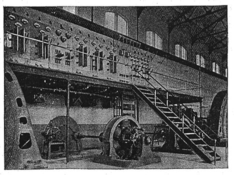
The switchboard, erected on a gallery on the north wall of the dynamo room, is built up of nine highly polished panels of blue Vermont marble, each panel 7 ft. 6 ins. high, 3 ft. wide, and 2 ins. thick. Of these nine panels five are used for the generators and two for the feeders; one is the total out-put panel and the last is for the control of the exciters. The generator panels occupy the left side of the board, and room on the gallery is left for two additional panels. The feeder panels are on the right hand side; the total output panel is between these and the generator panels and the exciter panel is the third panel from the left-hand end of the board.
Each generator panel is equipped with the following instruments: One inclined coil alternating am- meter reading to 75 amperes for the generator, and one direct current ammeter reading to 150 amperes for the field. Above each of these is a pilot lamp, and between each pilot lamp is a synchronizing lamp. Beneath the two ammeters is an inclined-coil voltmeter reading to 15,000 volts, and beneath this instrument are three single-blade double throw, quick-break, high-tension switches, which, seen from the front of the board, are each mounted upon pyramids of corrugated hard rubber. Similar pyramids intervene at the back of the board between the bus bars and the board. The corrugations give a total distance of about 8 ins. of surface between the metal clips and hinge, and the surface of the marble on each side. As these switches are to break a current of 12,000 volts, they are tested to break without difficulty currents of 21,000 volts. The switches are without handles. An eye is made in the end of each blade, into which a hook at the end of a stick may be inserted and the switch opened by the attendant from a sate distance. Further, to prevent any dangerous arcing from blade to blade, marble barriers 1 1/4 ins. thick, 3 ins. long and 12 ins. wide from the face of the board are erected between each blade.
 |
| Fig. 10. Type of Alternator Used. |
On the left-hand side oi each generator panel sub-base are two 100-ampere double-pole double-throw carbon-break switches one the field switch, the other the lighting switch. On the back of the panels are the high-tension fuse blocks.
These fuse blocks, designed tor 20,000 volts, are of the snap-break expulsion type. They are mounted on pyramids of corrugated hard rubber, which carry copper spring contact clips between which two copper blades enter, connecting the fuse block to the line. The aluminum fuse is held tightly between two arms, which are movable around a pivot, and may be pulled apart by two strong spiral springs incircling this pivot. As soon as an in:rease of current in the line melts the fuse, its two halves are instantly pulled apart and thus the formation of an arc between the two halves is prevented. The melting of the fuse can only occur in a small chamber protected by wooden blocks. The whole device is covered by two vertical wooden boards. Sliding in between these wooden boards in vertical slots are fibre shields intended to prevent arcing over beween the two arms after the separation of the two halves of the melted fuse. The two wooden blocks and fibre shields are held in position by four screws. The whole fuse block is inserted in the line simply by pushing the two blade-like copper contacts between the clip contacts, which are connected by solid copper rods to the bus bars. The wooden boards protecting the fuse are 10 1/2 ins. long and 6 3/8 ins. wide. The corrugated rubber pyramids on which the contacts are mounted are 3 1/2 ins. high. The field rheostats are hung beneath the gallery, and are operated by hand wheels on the gallery and bevel gears below it.
The exciter panel controlling the two direct current exciters carries two pilot lamps, two circular dial ammeters, each reading to 1000 amperes, one voltmeter reading to 150 volts, one four-point pressure switch, one synchronizing switch, two 800-ampere triple-blade double-throw equalizer switches and two packed card rheostats.
The two feeder panels are similar to each other in every respect. Each outgoing line is provided with an independent ammeter reading to 150 amperes and a quick-break double-throw high-tension switch similar to those on the generator panels, and similiarly mounted on the board. Mounted also on corrugated hard rubber pyramids are the six circuit breakers or automatic plunger switches.
The high potential plunger switches consist simply of long copper rods sliding in hard rubber tubes. The upper ends of the rods reach into small rings, in contact with which they are held by a lever catching a small rubber head. on the lower end of the copper rod. This lever is held in place by a spring, and is released by moving a rocker arm on the back of the switchboard. The moment it is released, a spiral spring pushes the copper rod downward, and by this movement, aided by the action of gravity, so suddenly is the contact broken that arcing between the rod and the ring is prevented. The rocker arm controls the three switches for each set of bus bars, so that they may all be released at once.
On the upper part of each feeder panel at the back is a current transformer for each outgoing line, two recording single-phase wattmeters, each reading to 25 amperes and 12,000 volts, and two potential transformers.
On the front of the out-put panel are two Thompson recording watt-meters for balanced three-phase circuits, each reading to 300 amperes and 12,000 volts, and twelve triple-pole single-throw 100-ampere switches with fuses for the lighting circuits. On the back are four potential and two current transformers.
The lightning arresters are of the G. E. short gap type. Arresters of this type have been installed on nearly all of the most important long-distance transmission lines in this country, and have proved a most satisfactory protection against damage by lightning.
| |||
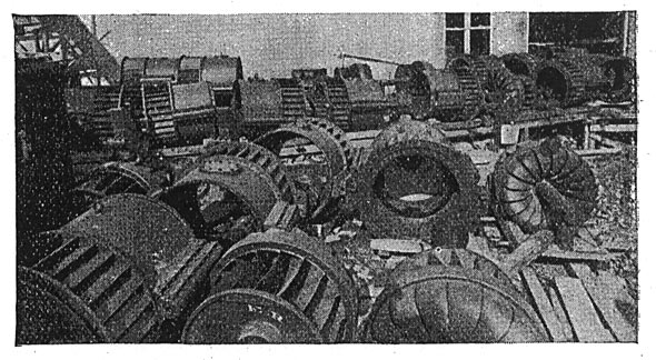
| Fig. 11. Turbines Before Installation. |
The principle on which this arrester operates is very simple. It allows the passage of any high potential discharge, but effectually prevents the alternating current from following and maintaining an arc. The gap spaces in, the lightning arrester at Mechanicville are very small about 1-32 ins., each space lying between two solid metal cylinders 2 ins..in diameter and 2 in; long. A low non-inductive graphite resistance is placed on the circuit, and the action of the arrester therefore is dependent upon the cooling effect of the large metal cylinders, aided by the reversal of the alternating current and the introduction of the non-inductive resistance. The line is protected by double-pole 2000-volt arresters, connected six in series to give the necessary number of spark gaps. There three sets of these, one at Mechanicville grouped around the first transmission pole in a small house 15 ft. square, one set on the Schenectady side of the Glenville bridge, where the overhead pole line connects with the underground cable, and the third at the works.
The lead covered leads from the generators are taken out at the base of the machine, and are laid in ducts in the floor. Rubber covered wire is used for the field connections. The cables rise on a frame from the duct to the floor of the gallery, through which they rise to the board. From the back of the board the line wires rise to supports bolted to the I-beam on the north wall, which supports one of the crane runways. The lines run along the north and west walls and pass out to the poles through a blind window over the door of the power house.
The line from Mechanicville to Schenectady is the only one at present laid down. It consists of three No. 000 B. & S. wires, this large gauge being employed in order to give the line as high a self-induction as possible. This insertion of self-induction in transmission lines is a departure from earlier practice. In cases where synchronizing apparatus is used self-induction is now considered necessary, and is artificially brought into the line in the shape of reactive coils in cases in which the natural self-induction is too small. The circuits are carried on poles of 30 to 60 ft. long and all 8 ins. in diameter at the top. Each pole carries one cross arm, on one side of which are two porcelain insulators of the petticoated type, a third being on the other side. For lightning protection a barbed wire frequently grounded runs along the top of the pole line.
The line takes a westerly direction to East Glenville and then due south to Schenectady. At the end of the Glenville bridge over the Mohawk the town limits it is carried down to the ground and connected to three cables of No. l gauge stranded copper, insulated by 1/4 in. rubber and 3-32 in. sheet lead laid in terra cotta conduits. These cables run 1700 ft. along Washington Avenue, rise to poles again through Rotterdam Street to the Erie Canal, and along the canal to a point directly opposite the General Electric power station. They here cross the canal and enter the General Electric Company's works.
The introduction of this transmitted electrical power into the factory will work a considerable change. At present all the machinery is driven by electric motors, while the testing department demands an independent supply of current for the work it carries on. There are at present, therefore, two distinct generating plants. The 550-volt motors in the testing department are supplied from an engine driven multi-polar generator of 500-k.w. capacity, while a smaller engine drives a number of exciters which allow of independent control of the excitation of all machines in this department. The factory is operated by a number of 250-volt motors, running on the same circuit as the factory lights. These motors will not be changed, and the steam plant which supplies them will be retained as a reserve in case the power from Mechanicville should fail. The electric power plant superseding the present steam plant at the works will, therefore, consist of two synchronous motors, one of 500 k.w., the other of 100 k.w., and three 400 k.w. rotary converters the synchronous motors for the testing department, the converters to supply current to the factory motors.
The large engine driving the 500 k.w. multipolar generator is superseded by the 500 k.w. synchronous motors. This is a twelve-pole 400-revolution machine of the revolving field type, wound directly for 10,000 volts. The small engine driving the exciters is replaced by the 100-k.w. synchronous motor and eight-pole, 600-r.p.rn. revolving-field machine similarly wound. This disposition renders this department independent of everything but the speed of the Mechanicville generators, which will be kept as nearly as possible constant.
The three rotaries supplying 250-volt current to the factory motors are ten-pole 400-k.w. 480-r.p.m. machines, having two commutators and two sets of collectors rings connecting to independent windings on the armatures. They receive the three-phase current from independent secondary coils of the same set of air blast transformers. When connected in multiple they furnish current at normal pressure of 250 volts, but as they may be called upon to furnish current to the testing department in case the demand exceeds the supply from the synchronous motor driven machine, they may be connected in series to give 500-volt current, operating in parallel with the 500-volt generator driven by the synchronous motor in the testing department.
| |||
| Fig. 12. View of the Power House, Showing Boom and Crib to Arrest Floating Refuse. |
The rotaries are operated in parallel and as well as all the factory lighting are operated from the same direct-current circuit, the latter on the Edison three wire system, the neutral wire of the three-wire system being secured, by connecting the transformers for the rotaries in Y with their secondaries and bringing to the neutral a lead from their common connection.
Synchronous motors were selected in preference to induction motors on account, first, of their more constant speed and greater efficiency; second, because they do not produce lagging currents, but the phase displacement and power factor may be controlled as desired by means of control of the field excitation.
Synchronous motors of the revolving field type and of good design are self-starting even under heavy load, and will easily carry two or three times full load without falling out of step for a time limited only by the heating of the motor.
To make the entire works system self-regulating in the direct current distribution and as far as possible independent of hand regulation, the rotary converters are given shunt field and powerful, series field, so joined together that the machines operate as one unit. With constant voltage in the generating station at no load, the counter e.m.f. of the rotaries as given by their shunt field is below the impressed e.m.f. and a lagging current is produced. The self-induction of the lines is thus in opposition to the voltage, which is so reduced as to give 250 volts at the commutator brushes of the rotaries. As. the load increases the counter e.m.f. of the rotaries rises, due to the series field, until at full and overload it is greater, than the impressed e.m.f., and the current becomes leading. The e.m.f. of self-induction of the lines is then brought partly in phase with the voltage, which is increased so that in spite of the increased line current and consequently increased energy loss in the line, with constant generator voltage, the same voltage is produced at the commutator brushes of the rotaries at no load as at full and overload. This control is therefore automatic in every way, and did the synchronous motor not take current over the same line in varying quantities would suffice. To render this control perfectly automatic, therefore, small series transformers are inserted in the lines leading to the synchronous motor, feeding a small synchronous motor generator controlling the shunt field of the rotaries. By the combined action of their shunt and series fields, the voltage is automatically maintained constant at the commutator brushes of the rotaries and no hand regulation is required beyond that of readjustment in case the number of rotaries in operation is changed. The works of the General Electric Company were fortunately situated to make use of this natural power, and the results will certainly add to the argument that the choice of factory sites within transmission distances of large water powers is advisable.
The entire construction of the dams, power house and lines has been carried out with the highest engineering skill by the National Contracting Company, of which G. M. Furman is general manager, B. A. Mathews superintendent and J. A. Leonard constructing engineer. The electrical equipment is furnished by the General Electric Company, and the hydraulic equipment by the Stilwell-Bierce & Smith-Vaile Company, of Dayton, Ohio, to which company was confided the entire development contract. It took the Hudson River in its natural state and turned the complete plant over to the operating company.
The officers of the Hudson River Power Transmission Company are: General Edmund Fayes, of Buffalo, N. Y., president; R. N. King, president of Stilwell-Bierce & Smith-Vaile Company, of Dayton, Ohio, vice-president; G. M. Furman, Newark, N. J., treasurer; B. J. Richards, Boston, Mass., superintendent, and J. S. O'Shea, manager.
