[Trade Journal]
Publication: Western Electrician
Chicago, IL, United States
vol. 30, no. 23, p. 399-401, col. 1-3
Missouri River Power Company's
50,000-volt Transmission.
The use of very high voltages for electrical power transmission over long distances is being watched with great interest by the engineering world, so that much importance is attached to a plant that actually employs for commercial service the transmission of current at 50,000 volts. Such a plant is that of the Missouri River Power Company. This company's installation was completed and the apparatus placed in operation early in March of this year, and since the starting of the plant it is stated that there has been no mishap of any kind to the line or apparatus. This is regarded as somewhat exceptional in undertakings of this magnitude and character, since it is generally expected that at the start minor difficulties are liable to be met with, which, though possibly not serious, will nevertheless affect the continuous service of the plant. Much of the credit for the successful operation of the plant is due to the general manager and engineer of the company, M. H. Gerry, Jr., who planned and executed the general undertakings, as well as to the Westinghouse Electric and Manufacturing Company, which furnished the electrical equipment.
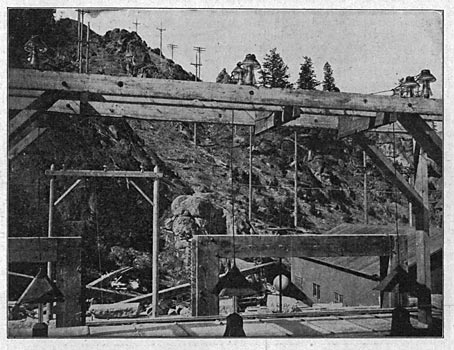
The present power house of the Missouri River Power Company is located on the Missouri River, about 20 miles almost directly east of Helena, Mont. To those who are familiar with the early history of the Northwest, it will be recalled that, in the famous Lewis and Clarke expedition of 1803-4 up the Missouri River and across the continent to the Pacific, one of the resting places and points of interest spoken of is Black Rock Canyon, met with soon after entering the Rockies at the mouth of the mountains, which is some miles to the east. Black Rock Canyon is not now known by this name, but at the mouth of the canyon lie the present little town of Canyon Ferry and the power house of the Missouri River Power Company. A general view of the power house and portion of the town is given in Fig. 1, which shows them located in a country not as rough as some parts of the Rocky Mountain, district, but by no means level. The district immediately about Canyon Ferry has been one of the famous gold-mining camps of the West, the discovery of gold having been made there in 1863. Placer mining is the more common way an which mining has been carried on, and it can be seen to-day, to a limited extent, within a mile or so of the power house.
 |
| (Left)Fig. 1. General View of Power House, Dam and Surroundings at Canyon Ferry. (Center)Fig. 2. Interior of Power House. (Right)Fig. 3. Three High-Tension Lines From Over the Hill Above the Power House. Missouri River Power Company's 50,000-Volt Transmission. |
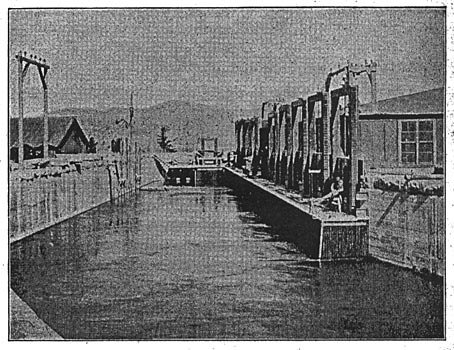
At the mouth of the canyon, a dam has been thrown across the river, about 480 feet in length, and designed to give a 30-foot head of water. The location of the dam at Canyon Ferry had enabled the company to take advantage of a low-lying valley just above the entrance of the canyon, in which to hold at all times a large volume of water in reserve. At the upper end of the canyon the water spreads out over this valley, forming a lake about seven miles long by two to three miles wide. The canyon by which the water comes to the power house is from 400 feet to 700 feet wide, and less than one-half mile long. The water in it does not freeze over in winter, and although the lake above freezes over, water is said to flow to the power house as free from ice in winter as in summer. The amount of water in the river at this point is considered sufficient to develop 10,000 horsepower the year around.
The project for a power plant at Canyon Ferry was first started about 10 years ago. The men who probably have taken a more continuous and extended interest in the proposition are Barton Sewell of New York city and ex-Governor Hauser, one of the pioneers of Montana and more thoroughly identified, probably, than any other living man, with that state's history and interests. About four years ago the decision to carry out the work at Canyon Ferry took definite shape, and work was started on a plant of 4,000 horsepower. This plant consisted of four 750-kilowatt, 550-volt, two-phase Westinghouse generators, driven by Dayton Globe Iron Works' waterwheels, with two 90-kilowatt exciters, driven by independent wheels. The current from these generators was raised by eight oil-cooled transformers from 550 volts to 10,000 volts and transmitted to Helena and East Helena, 20 miles and 14 miles away, respectively. At Helena the current was used, after transformation to 2,200 volts, for driving induction motors, direct-connected to arc-light machines, supplying city lights, and for distribution for general incandescent lighting. Two rotary converters, furnishing current to the street-car system of the city, were also supplied. At East Helena the current was used mostly for driving induction motors in the large smelter located there and for general lighting about the works. One line from Canyon Ferry also furnished power and lights to a large ore concentrator between Helena and East Helena, known as the Peck concentrator. The line between Canyon Ferry and Helena consists of but one pole line, carrying, however, four independent circuits, one, to East Helena, one to the Helena, one of the latter for lighting and the other for railway work.
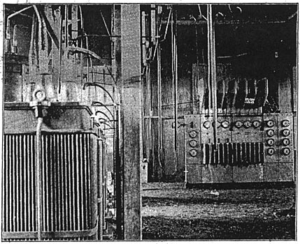
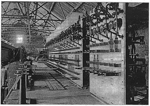
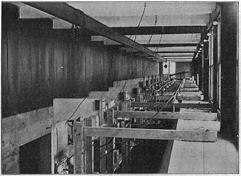
In the fall of 1900 work was begun at Canyon Ferry, with a view of making a very considerable extension of the company's plant, the proposition being to enlarge the plant to a capacity of 10,000 horse-power by putting in additional generators, with exciters, transformers, etc., and to extend the service to Butte, Mont., where it was expected that all the power the company might furnish could be sold. To this end the company has installed six additional 750-kilowatt Westinghouse generators, with the necessary transformers, exciters, etc. These generators are of the same size and voltage as the first four, but are three-phase instead of two-phase. The waterwheels are 45-inch horizontal; McCormack wheels, furnished by S. Morgan Smith of York, Pa. All generators in the power house are direct-connected to the wheels, flexible couplings being used throughout. With the new generators there was also installed a 225-kilowatt, iso-volt exciter, driven by a separate wheel, and a 115-kilowatt, 150-volt exciter, driven by an induction motor. To sum up, the power plant now consists of 10 750-kilowatt direct-connected generators, with four exciters, of which two are 90-kilowatt machines, direct-connected to separate wheels, one a 225-kilowatt machine, with a separate wheel, and one a 115-kilowatt, motor-driven generator. To make the plant uniform throughout, the four old generators have been overhauled and changed from two-phase to three-phase. Fig. 2, which is a general view of the inside of the power house, shows the row of generators, those in the foreground being new ones and the last four being old machines. The general plan of the station is shown by the outline sketch (Fig. 4), and, as will be noted, the switchboard gallery is on the lower side and directly over the waterwheels. Each water-wheel has its own governor, all the new and one of the old wheels having Lombard governors, and the remaining old wheels Replogle governors.
 |
| Fig. 4. Missouri River Power Company's Plant. Plan of Generating Station. |
The switchboard gallery, shown on the right of Fig. 2, extends the whole length of the building, and, besides supporting the switchboards, carries also 12 550 to 10,000-volt, oil-cooled transformers for the Helena and East Helena service, as well as a plug board for connecting these circuits as needed under various conditions. The offices of the company will be located on the floor extending across the building at the end from which the view (Fig. 2) is taken.
 |
| Fig. 6. Arrangement of Wires. 50,000-Volt Transmission Pole-Line Details. |
 |
| Fig. 7. Insulator With Glass Sleeve. 50,000-Volt Transmission Pole-Line Details. |
The main switchboard and exciter switchboard, shown in Fig. 5, are both, relatively, simple boards in design, but massive and substantial in construction. The main board is 47 feet four inches long and consists of 17 panels of blue Vermont marble, two inches thick. The weight of the board complete is about 20 tons, the copper alone being one half of this weight. The general arrangement is as follows:
| |||
| Fig. 5. Missouri River Power Company's 50,000-Volt Transmission. Main and Exciter Switchboards. |
The first five panels at each end are generator panels. The next two panels are feeder panels, and are intended for use with the 550 to 10,000-volt transformers. The eighth panel from the end on each side supplies a bank of transformers, 550 to 50,000 volts, for the Butte lines. The middle panel is a junction panel, so that any set of bus-bars on the two ends of the boards can be thrown together, there being three sets of bus-bars on each end of a board. The instruments mounted on the board consist of eight 750-volt, alternating-current volt-meters, one for each set of buses, and one at each end for the machines, independently of the buses; 10 direct-current field ammeters, 28 alternating-current ammeters, with 16 indicating polyphase watt-meters and six recording polyphase wattmeters. The recording wattmeters are behind the board. The exciter board consists of four panels of blue Vermont marble, similar to the main board, one for each exciter, with two sets of bus-bars. All field rheostats are mounted under the gallery floor and are controlled by hand-wheels, the shafts of which come up through pedestals in front of the boards.
| |||
| Fig. 8. Missouri River Power Company 50,000-Volt Transformer Room. |
The feature distinguishing the Missouri River Power Company's plant from all other transmission plants is the high voltage employed on its new lines to Butte. This is 50,000 volts, which is probably higher than is in use commercially on any other plant at the present time. The distance by pole line from Canyon Ferry to the Butte sub-station is 65 miles, the route corresponding nearly with that taken by the Great Northern railroad between East Helena and Butte. The line starts out at an altitude of about 4,000 feet above sea level at Canyon Ferry and gradually rises until it reaches an altitude of 7,300 feet where it passes over the Great Divide, a few miles east of Butte.
Fig. 3 shows the three high-tension lines from just over the hill above the power house. The two lines on the left are the lines to Butte operating at 50,000 volts. The 12-wire line on the right is the 10,000-volt line to Helena. The view shows a fair sample of the country through which the lines run.
| |||
| Fig. 9. Missouri River Power Company Forebay, Gates and Transformer House. |
The 50,000-volt transmission itself consists of two lines of poles about 50 feet apart, the cables being arranged in an equilateral triangle, with a spacing of 78 inches between centers, as shown in Fig. 6. Each line consists of three seven-strand copper cables, each cable having a cross-section of slightly over 106,000 circular mils. These cables are transposed five times between Canyon Ferry and Butte. The average distance between the poles is 110 feet. Fig. 7 shows a drawing in cross-section of the insulator used on the line, together with the glass sleeve fitting over the pin below the insulator. It has been found, after making exhaustive tests, that a thoroughly dry oak pin of the length used in this installation, boiled in paraffin, will readily hold up alone under 50,000 volts.. Hence, the object of the glass sleeve below the insulator is to keep as great a length as possible of the pin dry uftder all conditions of weather.
| |||
| Fig. 10. High-Tension Buses and Outgoing Wires at Generating Station. Missouri River Power Company's 50,000-Volt Transmission. |
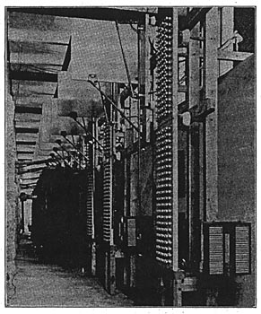
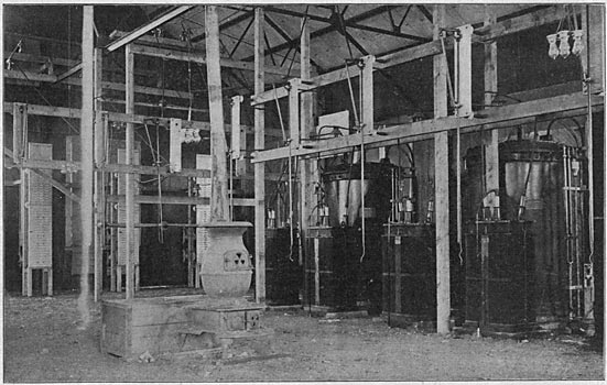
The transformers at each end of the line consist of six 950-kilowatt, oil-insulated transformers, with water-cooling coils in the cases. Those at Canyon Ferry transform from 550 to 50,000 volts and are shown in Fig. 8, which is a general view of the high-tension, 50,000-volt transformer room, taken from the north end. The picture also shows the lightning arresters, high-tension switches, barriers, etc. This room is located immediately back of the switchboards, and is shown from the outside by Fig. 9 (a view of the forebay, gates and transformer building), being just over the intake pipes for the wheels. Fig. 10 is a view taken from the same end of the building as Fig. 8, but from above, showing the high-tension buses and the method of coming into the building with the high-tension wires through the roof. The method used in leaving the outside of the building by high-tension lines, is illustrated in Fig. 11. Long glass tubes, similar to those used in transformers, are employed and are protected as shown.
At Butte the high-tension lines enter a frame sub-station at one end of the building, and the low-tension distribution is made by two pole lines from the opposite end. The transformation here is from 50,000 to 2,200 volts, and the secondary circuits consist of 600,000-circular-mil bare copper cable.
| |||
| Fig. 11. High-Tension Wires Leaving Roof of Generating Station. Missouri River Power Company's 50,000-Volt Transmission. |
A general inside view of the Butte sub-station, showing two transformers of one bank with static interrupters, high-tension switches, lightning arresters, etc., is given in Fig. 12. Fig. 13 is a view looking in an opposite direction, and includes the low-tension, 2,000-volt switchboard.
| |||
| Fig. 12. Missouri River Power Company's 50,000-Volt Transmission Interior of Butte Sub-Station. |
The customers of the Missouri River Power Company at present number nine, as follows: At Helena and East Helena, the Helena Power and Light Company, Helena and Livingston Smelting and Reduction Company, American Smelting and Refining Company and Big Indian Mining Company; at Butte, the Anaconda Copper Company, Butte and Boston Copper Company, Colorado Smelting and Mining Company, Boston and Montana Copper Mining Company and Washoe Copper Company. The general offices of the Missouri River Power Company are at Helena, Mont., and the New York office is at 71 Broadway. The officers of the company are: President, Barton Sewell; vice-president, W. S. Gurner, Jr.; secretary and treasurer, H. Suhr; general manager and chief engineer, M. H. Gerry, Jr.
| |||
| Fig. 13. Missouri River Power Company's 50,000-Volt Transmission Low-Tension Switchboard in Butte Sub-Station. |