[Trade Journal]
Publication: Western Electrician
Chicago, IL, United States
vol. 30, no. 11, p. 174-176, col. 1-3
Grand Rapids, Holland and Lake
Michigan Rapid Railway.
BY GEORGE A. DAMON AND WILLIAM D. RAY.
The Grand Rapids, Holland and Lake Michigan Rapid Railway company was incorporated on February 24, 1900, to construct and operate an interurban electric railway from Grand Rapids, Mich., the second city of the state, to Holland, and there connect with the Holland and Lake Michigan railway and the Saugatuck, Douglas and Lake Shore railway. From Grand Rapids, the eastern terminus, the road passes through the towns of Grandville, Jenison, Hanley, Jamestown, Vriesland and Zeeland, as indicated on the map, Fig. 1. A good farming country, an old and thickly settled rural community peopled by industrious Dutch and Germans, and given over to cultivation of acreages and fruit culture almost entirely, lies between Grand Rapids and the lake. Holland is practically the western terminus of the road. The total population served by the road outside of Grand Rapids is over 30,000.
 MICHIGAN RAPID RAILWAY.'> MICHIGAN RAPID RAILWAY.'> |
| Fig. 1. Grand Rapids, Holland and Lake Michigan Rapid Railway. |
The Holland and Lake Michigan railway and the Saugatuck, Douglas and Lake Shore railway were lines constructed for summer-excursion business. The eastern shore of Lake Michigan has for years been a favorite with residents of Chicago, who have visited Macatawa, Ottawa Beach, South Haven and other points in large numbers, and it is expected that the summer business of the interurban line will be very large.
TRACK CONSTRUCTION.
The Holland and Lake Michigan and the Saugatuck and Douglas electric lines operate over private rights-of-way for a distance of 16 miles, except for three miles through villages. The aggregate length of track of the combined roads is 71 miles. The total distance covered is 43 miles, 19 miles of this comprising the two roads running from Holland to the lake, acquired by the company. Twenty-six miles of double-track road has been laid by the new company, to reach Grand Rapids, from these lake resorts. Cars are operated on a headway of one hour and require at the present time one hour and 30 minutes for the trip from Grand Rapids to Holland, or three hours for the round trip. This time is to be reduced as the roadbed is bettered, and, later, during the summer, months, a maximum speed of'45 miles per hour will be realized, with an average speed of 26 mile's per hour, including stops.
| |||
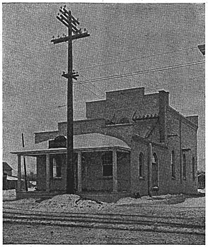
| Fig. 2. Grand Rapids, Holland and Lake Michigan Rapid Railway. Zeeland Sub-Station. |
 MICHIGAN RAPID RAILWAY. ZEELAND SUB-STATION.'>
The general character of the territory between terminals is, rolling, with some steep hills. Several wooden bridges for spanning creeks were required, the longest being that over the Lake Shore railroad near Grand Rapids, which is 750 feet in length and 24 feet in height at the apex, with grades of 1.59 and three per cent.
It is exceptional to find double tracks provided for in the original construction plans of an electric interurban. In this case such provision was wise forethought rather than compulsory afterthought, as the company's single-track steam-railroad competitor, the Pere Marquette, parallels the double track interurban from Grand Rapids to Holland. The track is standard gauge and laid with 67-pound and 70-pound rails, ballasted with gravel and well drained, where required, with vitrified tiling 12 inches to 36 inches in diameter. The sharpest curve is of six degrees and the maximum virtual grade is three per cent., except, at the subway in Holland, which is 5.56 per cent.
 MICHIGAN RAPID RAILWAY. SECTION OF POWER HOUSE.'> MICHIGAN RAPID RAILWAY. SECTION OF POWER HOUSE.'> |
| Fig. 3. Grand Rapids, Holland and Lake Michigan Rapid Railway. Section of Power House. |
The bonding of the rail joints was done vefy thoroughly. Two types of bonds were installed a foot bond on relaying rails where angle bars did not permit the usual web bond, and on all new rails a web bond.
Substantial depots for the small villages and shelters at highway crossings have been placed where warranted and are greatly appreciated by the patrons. The sub-station buildings at Zeeland and Macatawa are combined with a waiting room and freight office. The attendant for the electrical machinery looks after the selling of tickets, handling of freight, etc. The sub-stations are of white brick and stone construction with high elevation. Fig. 2 shows the Zeeland sub-station building.
POWER PLANT BUILDING.
The selection of the exact location of the power plant was the result of a desire to have the plant in or near the village of Jenison, and at the same time upon a site convenient to railroad facilities, and to a supply of water for condensing purposes. In the power-plant building itself, and, in fact, in the general design and selection of the entire equipment, an effort has been made to follow the best engineering practice and yet accomplish the result at minimum cost.
 MICHIGAN RAPID RAILWAY. PLAN OF POWER HOUSE.'> MICHIGAN RAPID RAILWAY. PLAN OF POWER HOUSE.'> |
| Fig. 4. Grand Rapids, Holland and Lake Michigan Rapid Railway. Plan of Power House. |
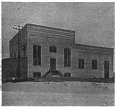
The general arrangement of the power plant is shown in section and plan in Figs. 3 and 4. The plant at present contains but two generating units. To furnish power for the operation of the road up to its full capacity with frequent and heavily loaded cars will eventually require double the present equipment, so that the necessity of providing for extension became in this case one of the first considerations. The engine and boiler rooms were, therefore, arranged in parallel, and a temporary bulkhead takes the place of one of the end walls, so that the present plant may be considered as just one-half of a completed station. The engine room is 32 feet high, 47 feet wide inside and at present 72 feet long. The engine room has a basement 12 feet high for the accommodation of the condensers and much of the steam piping; this basement is four feet below the boiler-room level. The boiler room is 54 feet wide, 28 feet high and the same length as the engine room. The building itself (Fig. 5) is made of cream-colored local brick, and has large windows, giving plenty of light and ample ventilation.
| |||
| Fig. 5. Grand Rapids, Holland and Lake Michigan Rapid Railway. Power House. |
 MICHIGAN RAPID RAILWAY. POWER HOUSE.'>
BOILER-ROOM EQUIPMENT.
The fuel is slack coal, which is received from cars delivered upon a trestle alongside of the boiler room by the railroad company. The coal-handling apparatus consists of a traveling bin carried upon an elevator leg which rests directly upon and travels along a track parallel to the boiler-room wall. At frequent intervals along this wall cast-iron pockets with sliding gates are placed ready to deliver the coal from the bunkers directly into the bottom of the elevator. the bucket system of which is operated by an electric motor, allowing the bin to be filled from any point of the coal storage.
| MICHIGAN RAPID RAILWAY. PLAN OF POWER HOUSE.'> |
| Fig. 4. Grand Rapids, Holland and Lake Michigan Rapid Railway. Plan of Power House. |
From the furnace hopper the coal drops onto a Green chain grate, made by the Green Engineering company of Chicago. Each boiler is fitted with a grate having an area of 53 square feet and guaranteed to handle successfully from 30 to 50 pounds of coal per square foot per hour.
The boilers are of the Cahall sectional water-tube type made by the Aultman-Taylor company. There are four boilers, each having 2,650 square feet of heating surface, made up of two steam and water drums 36 inches in diameter and 20 feet long, and 126 four-inch tubes, 18 feet long. These boilers and furnaces are guaranteed to transform at least 70 per cent. of the heat units of the fuel into energy in the form of dry steam at 150 pounds' gauge pressure and under full-load conditions will probably do even better.
| |||
| Fig. 5. Grand Rapids, Holland and Lake Michigan Rapid Railway. Power House. |
The hot gases are conducted by means of a sheet-steel breaching directly to the intake of a Sturtevant induced-draft fan. This fan discharges into a stub stack five feet in diameter, made of sheet steel, and mounted directly over the fan outlet. The top of this stack is only 40 feet above the grates, but this height has proved sufficient to operate the plant upon light loads without the use of the fan.
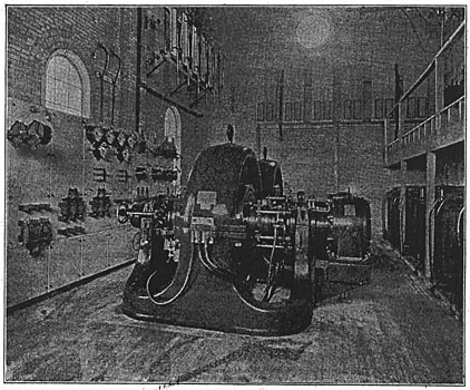
ENGINES.
The engines are rated at 750 horsepower each when running at 150 revolutions per minute and taking steam at 150 pounds' gauge pressure. They are of the vertical Ball & Wood cross-compound Corliss type, with cylinders 21 1/2 and 45-inch by 24-inch stroke. Each engine has a governor wheel 96 inches in diameter and weighing 16,000 pounds, which is mounted between the main bearings. Both engines and generators are of the direct-connected type, but the method of connection departs, somewhat from standard practice. The engine shaft extends beyond the main bearings a distance sufficient to receive the, hub of a flanged coupling. The revolving fields of the generators are carried on an independent shaft resting in two adjustable-bearings through which the generator shaft extends to receive the other half of the flanged coupling. The halves of the couplings on the engine and on the generator are thus in position to be connected by means of three taper bolts. In this way the generators are built and installed entirely independent of the engines. The generators being independent of the engines, it is possible to shift the generators from one engine to another in case of accident to either the engines or the generators.
ELECTRICAL EQUIPMENT.
The alternators are of the three-phase, 25-cycle, rotary-field, stationary-armature type, of 500-kilowatt capacity, made by the Westinghouse Electric and Manufacturing company, and are provided with armature-sliding frames, to permit access to all windings for repairs without requiring use of a crane. They have 20 poles and operate at a speed of 150 revolutions per minute. The rating is 722 amperes per terminal. The two exciter dynamos are 125-volt and of 30 kilowatts each, and either is sufficient for supplying full field current for the two alternators. The alternator armatures are star-connected and of the slotted-drum type. The armature has large ventilating ducts and is substantially constructed. The direct-current exciter generators are direct-connected to horizontal simple engines, running at 300 revolutions per minute.
 MICHIGAN RAPID RAILWAY. DIAGRAM OF SWITCHBOARD CONNECTIONS.'> MICHIGAN RAPID RAILWAY. DIAGRAM OF SWITCHBOARD CONNECTIONS.'> |
| Fig. 6. Grand Rapids, Holland and Lake Michigan Rapid Railway. Diagram of Switchboard Connections. |
The switchboard consists of 10 panels, all of blue Vermont marble, mounted on the usual framework of angle irons, distributed as follows: One exciter panel (two exciters), two alternator panels, two transformer panels, two alternating-current rotary panels, two direct-current rotary panels, one direct-current-trolley double-feeder panel. This switchboard is of the Westinghouse standard pattern. The principal features of the board are a totalizing, integrating wattmeter, placed on each alternator panel; a double, low-tension bus-bar arrangement for flexible manipulation of alternators, with transformers and rotary converters, and separate ammeters for each phase, reading to 1,200 amperes. Synchronizing lamps and shunt transformers are used, when machines are to be synchronized with bus-bars. A wiring diagram of the switchboard is given in Fig. 6.
| |||
| Fig. 7. Grand Rapids, Holland and Lake Michigan Rapid Railway. View of Double Track. |
 MICHIGAN RAPID RAILWAY. VIEW OF DOUBLE TRACK.'>
The step-up static transformers, which are located in a gallery, are of the Westinghouse oil-cooled type, and are seven in number (two sets of three each and one spare), each being of 200 kilowatts' capacity. The ratio of conversion is one to 50. Two 300-kilowatt rotary converters are installed in the power house for handling the sections of the line adjacent to the power house. The rotaries are started by an induction motor, direct-connected to the armature shaft, and synchronized by means of lamps connected on one side to the bus-bars and on the other to the alternating-current side of the rotaries.
| |||
| Fig. 9. Grand Rapids, Holland and Lake Michigan Rapid Railway. Closed Car. |
 MICHIGAN RAPID RAILWAY. CLOSED CAR.'>
Each governor arm of the 750-horsepower engine, driving the alternator, is equipped with a series-wound one-fourth-horsepower, 125-volt Sprague electric motor, for controlling the speed of the engine in synchronizing generators. The control of this motor is from special switches and rheostats on the switchboard.
For some months past a 1,000-kilowatt rotary converter has been in operation, pending the delivery of permanent alternators. This machine is belted to a special pulley flywheel on the engine shaft and runs at 300 revolutions per minute. A 5.62-kilowatt, 500-volt exciter dynamo is belted to the shaft of the rotary and supplies the fields with current. A three-phase alternating current of 380 volts is delivered to static transformers and a direct current, approximating 600 volts, or such voltage as follows the departure of the generator from a true sine wave, is delivered to the trolley wire of the line sections adjacent to the power house. This temporary arrangement has worked well, excepting for the regulation, which has been poor at times, occasioned by the reactive effects.
The station lights, consisting of some 65 incandescent lamps, are operated off of a special transformer of 125 volts' secondary and 400 volts' primary. After the shutdown of the plant at night, should light be required, the exciter dynamo is started and switches transfer this duty to the exciter.
The six high-tension wires after leaving the step-up transformer are interrupted at the high-tension board by six single-pole combination fuse switches or circuit-breakers. The lightning arresters on the line are of the Wurts type. In the station low-equivalent arresters are mounted on a marble panel 24 by 65 inches. One single-pole arrester is used on each end of each transmission line.
Static interrupters, which resemble transformers in external appearance, take the place of the choke coils commonly used, and are much more effective. The interrupters are single-pole, and three are used for each group of three transformers, the interrupters being placed in the leads of the delta.
LINE CONSTRUCTION.
Six aluminum wires of 52,630 circular mils each leave the Jenison power house, carrying current at 20,000 volts, and follow along the railway tracks westerly to the Zeeland sub-station, 15 miles distant, and at this sub-station these six wires pass through the building and continue on to the Macatawa sub-station, 10 1/2 miles from Zeeland. The six high- potential wires comprise two circuits.
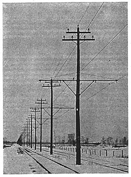
The poles are of 40-foot and 30-foot lengths, with seven-inch tops and 13 inches in diameter six feet from the base, and were shipped from L'Anse, a northern Michigan timber point. They are spaced 100 feet apart and are midway between tracks, which are 15 feet between centers, and are placed on an average of seven feet in the earth. A view of the double-track construction is shown in Fig. 7. At the side of each sixth pole is driven a 12-foot section of galvanized iron pipe, to which is connected a No. 6 copper, wire, leading directly to the top of the pole, arid tapped into a barb wire carried on a top-groove glass cable insulator. These pipes form a good earth connection for lightning discharges that may strike the high-tension circuits. The barb wire is of large size and composed of two No. 9 B. & S. wires.
Direct-current feeders of aluminum are also used. They are supported on the trolley brackets, rather than upon additional cross-arms. This method is not only neat and substantial, but less expensive than additional cross-arms.
On the 40-foot high-tension poles, a distance of five feet five inches is maintained below the telephone circuit and horizontal arm of brackets, with a separating distance of 20 inches between the two No. 10 copper telephone wires. The transpositions of the telephone wires occur every four poles, and a straight drive bracket, with a transposition glass insulator, is used. Thus far the telepnone circuit has been very sensitive and worked well, but as soon as a ground occurs, the circuit is then too noisy to hear ordinary speech. Telephones are installed at the power house, turnouts, sub-stations, offices and car barns. A dispatcher is employed to direct the movements of the cars by the medium of the telephone line.
The General Electric M. D. type of lightning arrester is installed, and four of these are placed to the mile, giving the most efficient lightning protection for the direct-current circuits. The trolley wire used is No. 000, figure 8 section. Section insulators in both trolley wires, bridged by 800-ampere circuit-breakers, are placed between the power house and Zeeland and the latter sub-station and Macatawa.
The old steam power plant at Macatawa, of 500-kilowatt capacity, has not been dismantled, but will be used during the summer months, when excessive loads on the Holland terminal require its operation.
SUB-STATION.
The main sub-station room at Zeeland, shown in Fig. 8, has interior dimensions of 39 feet eight inches by 27 feet, and contains two 300-kilowatt Westinghouse rotary converters, seven 120-kilowatt, step-down, oil-cooled transformers, six static interrupters and lightning arresters and six combination fuse switches; also emergency switches, for putting the high-tension circuits in multiple. At Zeeland switches for controlling the lines to Macatawa sub-station are provided. A seven-panel switchboard is installed, and all wiring under the floor was done with lead-encased cable. In the gallery, some seven feet above the floor, are placed the static interrupters, combination fuse switches and emergency switches. The switchboard consists of two transformer panels, two alternating-current rotary panels, two direct-current rotary panels and one direct-current double-feeder panel. A swinging bracket, holding two direct-current voltmeters, is attached to the latter panel. All transformers are earthed and are piped up, with individual valves on each transformer, for draining oil from the cases.
CAR EQUIPMENT.
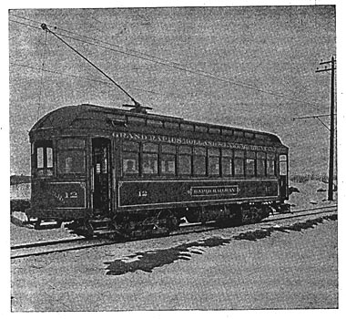
Six closed passenger cars 47 feet long, of the type illustrated in Fig. 9, and four closed passenger cars 41 feet long, with motorman's cab on one end only, are already in operation. The cars were furnished by the Jewett Car company and the G. C. Kuhlmann Car company. They are finished in cherry and oak, and are provided with smoking compartments or baggage compartments.
The trucks are of the Peckham type, with outside-hung brakes, and are equipped with four Lorain Steel company's No. 34 motors, of 50 horsepower each, with inside-hung, rigid suspension. The current required to start a car is 175 amperes, and the normal running current is 135 amperes at 500 volts. The cars are heated by the Peter Smith hot-water heaters. All cars are equipped with the storage air-brake system, furnished by the Magann Air Brake company. The air reservoirs are charged from a large storage tank, set between the two tracks, at Jenison, 900 feet from the power house. The air compressor is a part of the power-house equipment. An additional air compressor of the belt-driven type is placed in the Macatawa sub-station and operated by a series electric motor.
| |||
| Fig. 8. Grand Rapids, Holland and Lake Michigan Rapid Railway. Interior of Zeeland Sub-Station. |
 MICHIGAN RAPID RAILWAY. INTERIOR OF ZEELAND SUB-STATION.'>
The company has recently ordered five 50-foot passenger cars, which is proof that the long cars are considered best suited for its interurban business. It is confidently expected that trains of two cars will be necessary for handling the summer business. Ultimately, the shorter cars will run during .that part of the day when travel is light. The road also has, in addition to this car equipment, three 35-foot closed passenger cars and seven 35-foot, 12-bench, open passenger cars, equipped with two 35-horsepower motor Walker equipments. These cars are mounted on maximum-traction trucks.
A terminal barn and shop are located at the Macatawa sub-station, and another will be built in the spring at Jenison. A feature of the latter barn is that the main tracks pass through the barn and are provided with inspection pits. Every car will receive an inspection of motors, wheels and trucks on every round trip.
The freight equipment consists of three 35-foot closed cars, similar in exterior appearance to those used for passenger purposes. The company has six 26-foot box cars and six 30-foot gondolas; also one combination freight locomotive and nose snow plow and one Ruggles rotary snow plow. These snow plows have done excellent work during the last winter.
CONCLUSION.
The rates for freight are low, ranging from 2 1/2 cents to 23 cents per 100 pounds, dependent upon distance, rate basis and classification. The express rates vary from 20 cents for a package weighing not more than 10 pounds to 45 cents for packages weighing from 50 to 100 pounds.
Village franchises call for a rate not to exceed 1 1/2 cents per mile for carrying passengers, with no fare accepted less than five cents, but the steam-railroad competitor has recently reduced its rates, and as a result the interurban company is making special rates, during certain hours of the day, when the steam road has trains moving between terminal points.
The Grand Rapids, Holland and Lake Michigan railway was financed and built by the Detroit Construction company of Detroit, of which John Winter is president. The electrical-engineering work was under the direction of W. D. Ray, at that time electrical engineer for the Detroit Construction company. The contract for the complete power plant including the building, was awarded to the Arnold Electric Power Station company of Chicago, and this part of the work was done in accordance with plans and specifications submitted by the Arnold company.
Abstract of paper read before the Chicago Electrical association on March 7, 1902.
