[Trade Journal]
Publication: Western Electrician
Chicago, IL, United States
vol. 38, no. 1
Fisk Street Station of the Commonwealth Electric Company, Chicago.
CENTRAL STATION practice in Chicago at the present time exemplifies many ways the highest development of the art. A city with a population of nearly 2,000,000 souls, distributed over an area about 26 miles long and averaging some eight miles in width, with a central portion which is densely congested by business requirements, offers a great variety of problems to the central-station management.
Fifteen years ago several central-station companies were operating in the city, among them the Chicago Edison Company, which was the largest. To-day, however, a different state of affairs exists, and all the smaller independent companies have given place to the two large companies which now control Chicago's, central-station business the Chicago Edison Company and the Commonwealth Electric Company. Each generates and distributes electricity in its own territory, that of the Edison being the central portion of the city and that of the Commonwealth the surrounding parts. However, the two systems are interconnected, and that of the Chicago Edison Company receives much of its current from the principal generating plant of the Commonwealth Electric Company. This generating plant is known as the Fisk Street .Station, the first steam-turbine central station to be put in operation. Equipped entirely with steam turbines and the most modern apparatus, and with an ultimate capacity of 156,000 kilowatts, the Fisk Street Station, from its great size and many new features, is one whose development has been followed closely by engineers and others interested in central station practice. It is the purpose of the present article to describe the plant as it now stands, with four large units complete. The previous articles which have appeared in the Western Electrician, notably that of May 23, 1903, were more preliminary in character.
| |||
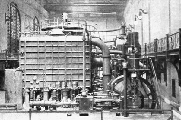
| Fig. 1. Interior View in Fisk Street Station, Showing Four Steam Turbines Now Installed. |
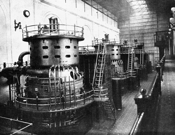
It is to be noted that, whereas the three older units of the present equipment have a nominal rating of 5,000 kilowatts each, they have been run continuously at 6,000 kilowatts, and at times of peak load as high as 7,500 kilowatts each. The latest unit No. 4 which is the farthest from the spectator in the picture on this page, and separately illustrated in Fig. 7, has a maximum capacity of 9,000 kilowatts. As it stands at present the station has a record of carrying 28,500 kilowatts. But four more units have been ordered and will undoubtedly be placed in position during the year.
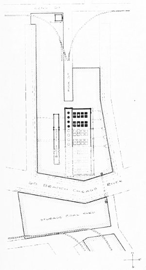 |
| Fig. 2. Plot of the Fisk Street Properties of Common-Wealth Electric Company. |
These, like their predecessors, are General Electric outfits with Curtis turbines. These turbo-generators will have a nominal rating of 8,000 kilowatts, guaranteed, however, to run continuously at 9,000 kilowatts, and for two hours, the period of maximum load, up to 12,000 kilowatts. This equipment will add 48,000 kilowatts to the capacity of the station, bringing the total up to 76,500 kilowatts.
| |||
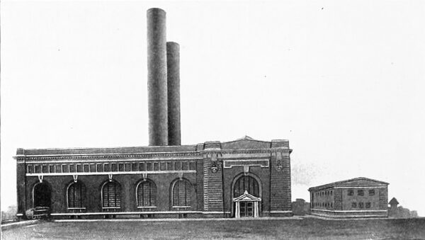
| Fig. 3. Exterior of Fisk Street Station of Commonwealth Electric Company (Switch House at Right). |
After this addition it is the intention to remodel the three older turbines now installed, so that no machine in the station shall have less than 9,000 kilowatts maximum capacity, while all after the first four will have 12,000. The plant is designed for an ultimate capacity of 14 turbines, so that the total ultimate capacity of the Fisk Street Station will be 156,000 kilowatts. It is believed that no other electric-light and power station anywhere is now planned to be so large as the Fisk Street plant when it is completed.
FISK STREET PROPERTIES
Fisk Street Station is located at the juncture of Fisk Street and the South Branch of the Chicago River, and is about three miles from the downtown business district. At this point the Commonwealth company owns 23 acres of land, the relative location of the property being shown in Fig. 2, the heavy outlines denoting the company's property. On the north, the tracks of the Chicago, Burlington and Quincy Railroad enter the grounds, as shown, and at the south end of the property, across the river from the station, the tracks of the Chicago and Alton gain entrance, so that coal and supplies may be obtained from two separate roads.
| |||
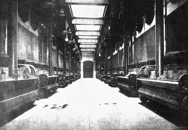
| Fig. 4. Interior of Fisk Street Boiler Plant, Showing Fronts of Two Boiler Units). |
Ample facilities for the storage of coal are provided, as will be seen by Fig. 2. not only across the river from the station, but on the same side as well, where sufficient trackage is provided, which, however, is not indicated on the diagram. As much as 60,000 tons has been in storage at once, and still the capacity was not taxed greatly. Coal is transported from the storage yard across the river to the station side by means of large scows or barges.
Most of the coal burned is screenings from the Springfield district, averaging about 10,500 B. T. U. The station has used as high as 1,000 tons in a day in December. This low-grade coal has been found very satisfactory and makes an intensely hot fire under the excellent firing conditions which exist in the plant. Combustion is nearly complete and very little smoke is noticeable; indeed, this 28,000-kilowatt plant emits less smoke than comes from a small nearby plant using an engine of probably a few hundred horsepower.
| |||
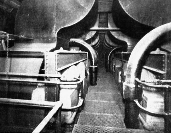
| Fig. 5. View Above Boilers in Fisk Street Plant, Showing Uptakes and Steam Piping. |
| |||
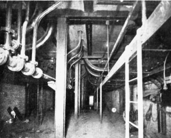
| Fig. 6. Heater Room Underneath Boilers. |
Located near the center of the property is the generating station and the switch house. The part indicated in heavy black in Fig. 2 is the present completed portion, the part indicated in solid lines is work now under construction and the part in dotted lines is for future extensions. The width of the station is approximately 230 feet. The completed portion (A) is 185 feet long, the portion under construction (B) is 165 feet in length, leaving for the future extensions the portion (C) which is 265 feet in length.
At the north end of the property, near Twenty-second Street, is a substation now in process of construction, which is known as the West Twenty-second Street Substation.
Generating Station and Equipment.
Fig. 3 is an exterior view of the Fisk Street Station as it now stands. The building is of the French style of architecture with red pressed-brick walls and cut-stone trimmings, the whole effect contrasting in a pleasing manner with the plain surroundings of the neighborhood. Reference to the accompanying supplement will show the general layout of the plant, both in plan and section. The unit idea pervades the whole installation, from the coal conveyors to the last outgoing line switch, each group or unit being complete in itself, with the idea of localizing and confining any possible trouble that might arise.
| |||
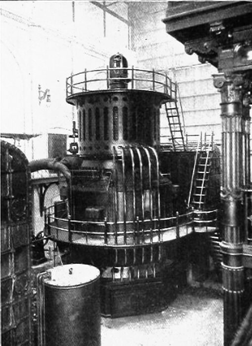
| Fig. 7. Steam-Turbine Unit No. 4 in Fisk Street Station (Maximum Capacity, 9,000 Kilowatts. |
On the eastern side of the building is the train shed, which extends the entire length. Here the coal cars are run in for unloading into hoppers below the floor, which discharge the coal into crushers preparatory to its entering the conveyor system. The crushers are motor driven, and one is provided for each boiler unit. From the crushers the coal is carried by Meade conveyors having 24 by 24 inch buckets to the coal bunkers, which are located above the boilers, the bunkers for each boiler unit having a capacity of 1,000 tons. The conveyors travel continuously and are utilized to remove the ashes from the pits beneath the boilers to a hopper above the railroad track, from which they may be discharged into cars.
Boiler Plant.
Each boiler unit consists of eight Babcock & Wilcox boilers, the boilers of each two consecutive units facing each other as shown in Fig. 4. The boilers have 5,000 square feet of beating surface, there being in each 52 four-inch tubes 18 feet long, arranged in banks 18 tubes wide and 14 high. Nominally, the pressure carried is 180 pounds to the square inch. The chain-grate stokers are driven from a shaft extending the full length of each boiler unit, this being driven by either of two engines, one of which is always held in reserve.
| |||
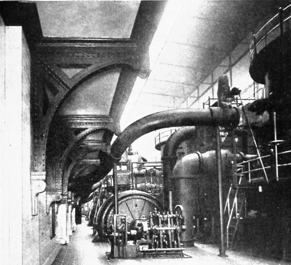
| Fig. 8. View in Turbine Room, Showing Headers Leading to Turbines. |
| |||
| Fig. 9. Condenser Installation for Unit No. 4. |
Coal from the bunkers above the boilers is brought down to the grates through swinging chutes, which distribute the coal evenly along the grates. The bunkers for each boiler unit having a capacity of approximately 1,000 tons. The entrance of the coal into the chutes is governed by a valve-like arrangement controlled by chains which are within the reach of the boiler attendant on the floor. The furnace gases pass from the flues through curved uptakes, shown prominently in Fig. 5, to the boiler breechings which lead into the stack. One stack is provided for each two boiler units. The stacks are of steel construction, rising to a height of 205 feet above the boiler-room floor and with an inside diameter of 18 feet. They are not built from the ground up, but are supported above the boilers.
| |||
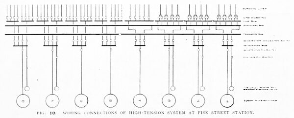
| Fig. 10. Wiring Connections of High-Tension System at the Fisk Street Station. |
Superheat of 150 is used, which is obtained by a superheater receiving the direct influence of the hottest part of the furnace gases. The superheated steam from each pair of boiler units passes from the superheater upward to a point above the boilers and from there into a six-inch pipe passing down to the main steam header located in the basement. In the view above the boilers (Fig. 5) the arrangement of a portion of this piping is shown in the foreground. Reference to the supplement will indicate more clearly the arrangement of the boilers and piping, since one portion of the plan shows the top of a set of boilers with the piping arrangement, another portion shows in plan the piping in the header room below the boiler-room floor, and the third portion, which shows boiler units 5 and 6, not yet constructed, is a plan through the pent house with roof construction removed.
| |||
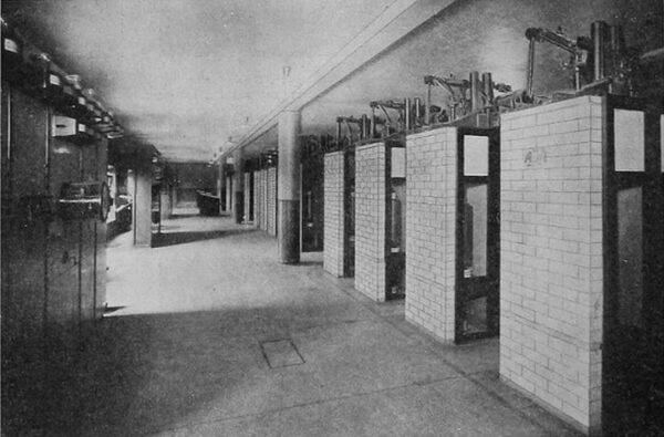
| Fig. 11. Oil Switches for First Four Units in Switch House at Fisk Street Station. |
In a separate compartment of the basement is a header room, as mentioned above, for each pair of boiler units. One of these header rooms is shown in Fig. 6. Two main steam headers, varying in diameter from five to 14 inches, extend lengthwise of the compartment, and into them are tapped the feeders as shown in the plan (see supplement), each pass into the turbine room, going direct to the turbines, thus preserving the unit idea. There is, however, an interconnection between each pair of main headers which will allow of one turbine being run from its adjacent boiler unit if desired. Remote-control motor-operated valves are used. In the header room there are also located the feed and auxiliary headers for the auxiliary apparatus.
In the basement below the boilers is located an air-compressor outfit, which furnishes air at go pounds pressure for operating window shutters and tools, cleaning electrical apparatus, etc. It is driven by a 35-horsepower motor, the whole being enclosed in a sheet-iron housing.
Steam-turbine Installation.
Above all other things that have made the Fisk Street Station a landmark in the progress of central-station development is the use of the steam turbine exclusively as the prime mover. This radical step was first taken in the Chicago plant, and the first 5,000-kilowatt steam turbine to be put in operation was here installed. Since the first turbo-alternator was put in, which was in the early part of 1903, three others have been installed, two identical with the first and the third possessing several improvements. The interior of the turbine room, as it now looks, is shown in Fig. 1. The fourth and last turbine to be installed is shown in the picture at the rear end of the room.
| |||
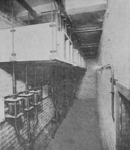
| Fig. 12. Instrument Transformers in Switch House at Fisk Street Station. |
The two-stage vertical Curtis steam turbine, made by the General Electric Company, has been frequently described, and it is hardly necessary here to take up in detail the features of its construction. The first three Chicago units are about 26 feet in height and 16 ½ feet in diameter, and are mounted on a foundation four feet above the floor, making the total height above the floor about 30 feet. In size and arrangement the buckets are so proportioned that the velocity of the steam, for any particular rotative speed, is only partially taken up in the first stage, the remaining part being practically all utilized in the second stage. So low is the velocity of the steam at exhaust that the exhaust openings are made of unusual size, and the condenser is placed close up to the turbine.
Governing is accomplished by the successive opening or closing of the various nozzles leading to the buckets. Each nozzle may be closed gradually, and can be worked continuously at any position between full-open and closed. The governor is mounted on top of the alternator and connected to the end of the vertical shaft.
As the first unit installed represented the first type of 5,000-kilowatt turbo-generator (nominal rating) built by the General Electric Company, so the last unit, or No. 4, represents the latest phase of its development, which, though essentially similar, contains some few- improvements as to detail. The essential points of difference between the No. 4 unit and the previous three are that the steam enters the turbine through two steam chests instead of three, as formerly, each of the two chests being provided with 15 electrically operated valves, making a total of 30 valves on No. 4 against 33 on the first three units.
The last turbine is a five-stage unit instead of two stage, and the generator, in accordance with recent designs of alternators by American manufacturers, has better ventilation and a somewhat lighter armature frame. The electrically operated valves have a greatly improved arrangement in construction.
The No. 4 unit is a trifle higher, but otherwise its general dimensions, weight and speed arc the same as for the first three units. Fig. 7 is a good view of unit No. 4.
The turbine room, as seen in Fig. 1. extends north and south and is at right angle of boilers forming each boiler unit. This is a radical departure from the usual practice of setting the lines of boilers parallel to the line of engines. The main steam headers pass in an upward direction direct to the turbines, as previously mentioned. Fig. 8 is an interesting picture showing these headers as they emerge from the partition beneath the visitors gallery and pass in sweeping curves to the various units.
| |||
| Fig. 13. Bus-Bar Compartment in Fisk Street House. |
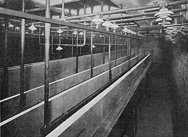
The long room in which the turbines are installed is handsomely finished in white glazed brick and terra cotta from floor to ceiling, with ornamental terra cotta architraves to all openings. A gallery extends along both sides, giving a good view of all the units. A railroad track enters the building at the main entrance on the north front, so that parts for each successive unit may be taken direct from the car and put in position by the 50-ton crane that serves the turbine room. The floors are of vitrified German tile of small size laid in a pattern which gives a general mosaic effect.
Condensers and Auxiliary Apparatus.
The surface condensers, containing 20.000 square feet of heating surface each, were furnished by the Alberger Condenser Company of New York city. These condensers are located close to the turbines and one of the units is shown in Fig. 9. For circulating the condensing water a centrifugal pump is used with each condenser, driven by a vertical Corliss engine, which is shown in Fig. 9. On the same shaft with the circulating pump is a vertical two-stage dry-air pump. The wet vacuum pump is installed as a tailpiece on the steam cylinder of the vertical engine.
Duplicate vertical boiler feed pumps, the hot well and the feed-water heater are located underneath or adjacent to the surface condenser, so that the entire equipment for each unit is compactly arranged as shown in Fig. 9. The boiler feed pumps take their supply directly from the hot well into which the condensers discharge.
Condensing water is taken from the slip on the east side of property, this being the upstream side, by means of one concrete tunnel for each two units. These tunnels deliver to wells from which the circulating pumps take suction. After passing through the condenser the circulating water is delivered to other concrete tunnels, one for each four or five units, which tunnels discharge into the slip on the west or down-stream side of the property.
 |
| Fig. 14. High-Tension Feeder System of Commonwealth Electric and Chicago Edison Companies. |
Excellent results thus far obtained indicate that the power required for driving these various condenser auxiliaries is extremely small, in fact a considerably smaller percentage of the total output of the generator than is the usual practice.
Other machinery which might in a general way come under the head of auxiliary apparatus includes a complete fire-protection system maintained by the station. For this purpose a spherical pump capable of delivering water up to a pressure of 200 pounds to the square inch is located in a separate room off from the turbine room. This pump is driven by a 225-horsepower General Electric motor. "By the use of a Cutler-Hammer control board, which is located in a sheet-iron housing in the pump room, the motor is automatically brought up to speed upon closing the switch.
Another important part of the auxiliary apparatus is the oil-pumping system for the step bearings of the turbines. This apparatus is located in the oil room, which opens out of the turbine room. The oil from the turbine bearing comes directly to the filters located in this room. After filtering it is taken to a storage tank, from which the various pumps supplying oil to the bearings derive their supply. To keep up the oil pressure in case of emergency a main oil pipe is provided which contains oil under 1,200 pounds pressure, the pressure supplied to the bearings, and derives its supply from a steam-driven pump, the pressure being also maintained by an accumulator similar in construction to the type of accumulator used in high-pressure hydraulic elevator systems. Oil for lubrication is supplied by a gravity system.
General Electrical Features.
Three-phase current is supplied by the turbo-alternators at 9,000 volts, 25 cycles. Each alternator, with its switching apparatus, forms a separate unit. While each of the different units will ordinarily be operated independently, provision is made whereby any unit can be connected in multiple with any other in reference to its group of feeders.
| |||
| Fig. 15. Main Operating Switchboard in Fisk Street Turbine Room. |
The high-tension installation for the station is located in the switch house, a two-story building with a basement, which parallels the main station at a distance of 50 feet (see Fig. 3). One-half of this building, to accommodate seven units, has been erected. At the present time the electrical installation for units 6 and 7 is in progress. The wiring connections for the high-tension system are shown in Fig. 10.
High-tension oil switches and instrument switch-boards are located on the first floor of the switch house, while the bus-bars and other high-tension connections, together with the instrument transformers and the necessary manholes and subways for the outgoing lines, are located in the basement. Fig. 11 is a view showing part of the oil switches for the first four units, and Fig. 12 shows the instrument transformers in the basement.
A distinctive and special feature in the design of the switch house is the isolation of all high-tension bus-bars and connections thereto in fireproof compartments. The oil switches, together with the instrument switchboards on the first floor have also been grouped in units, but not, however, in separate compartments. The control and instrument wiring in the switch house is brought to the controlling switchboard located in the operating gallery in the turbine room through separate groups of ducts for each unit.
| |||
| Fig. 16. Assembly and Reading Room for Employes of Fisk Street Station. |
As will be observed from the diagram of high-tension bus connections, the energy after leaving the turbo-generators in the turbine room is delivered by means of high-tension single-conductor lead-covered cables through an oil switch to the generator bus in the switch house. From this bus, in the first four units, the energy is delivered to three sets of busses, namely, transfer, auxiliary and line busses. The line busses for these four units are equipped with sectionalizing oil switches.
Beginning with the fifth and the following units, the generator bus is connected with four sets of busses, namely, transfer, auxiliary and two line busses. Here it will be observed there are no sectionalizing switches between the line busses.
In the first three units all lines are equipped with two selector switches and only four lines per unit. In the fourth and following units the lines are equipped with only one switch each, five lines emanating from the fourth and eight lines from each of the following units. The increased number of outgoing lines per unit is due to the larger size of turbines to be installed, beginning with the fifth unit.
There are installed at present three 50-kilowatt induction-motor exciter sets, on an inter-connected system. It is proposed to install two similar exciter sets in the portion now under construction. In each case these exciter sets are connected to the generator bus of that particular unit through an oil switch and a step-down transformer located in the switch house. In addition to these exciters there is an emergency steam-driven exciter which consists of a General Electric 127.5-volt 588-ampere generator direct connected to a vertical engine.
In the first four units the compartments for the high-tension bus-bars in the basement of the switch house are so arranged that all busses and connections to oil switches for each unit are contained in one compartment (see Fig. 13). The instrument transformers and underground cable connections for lines are also contained in a compartment by themselves and similar connections for generator leads are contained in another compartment, making three compartments per unit.
In the fifth, sixth and seventh units a feature of special interest has been introduced in the bus connections whereby each bus has a separate compartment and all oil-switch connections, together with the instrument transformers and bells for cables, are likewise contained in separate compartments, one for the generator and two for the out-going lines, a total of seven compartments per unit. By this arrangement it has been possible to separate and isolate all phases of busses and connections, including the instrument transformers, by means of concrete barriers, thus insuring reliability in operation, simplicity in design and economy in investment. The busses are arranged in a vertical position and supported on porcelain petty-coated insulators, while the oil-switch connections in all cases consist of copper rods practically self-supporting.
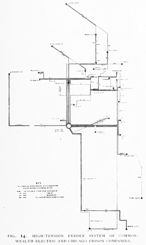
It is possible by means of the transfer and auxiliary busses, in case of any disability of any particular unit, to furnish the necessary energy for its lines from any other unit. Ordinarily the units are operated independently. The outgoing lines leave the station in three-conductor 0000 under-ground cables and are distributed to the various substations, as shown on the diagram of the transmission system, Fig. 14. This diagram illustrates admirably the relation of the Fisk Street Station to the combined system of the Commonwealth and Chicago Edison companies. As shown in Fig. 14, Lines Nos. 1 to 200 inclusive are from, the Fisk Street Station, 201 to 300 from the Morgan Street Station and 301 to 400 are tie lines between sub-stations.
Switchboard and Apparatus.
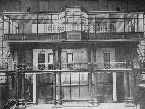
Remote-control apparatus which is used to operate, the switches in the switch house is contained in an elevated switchboard room which is built up on the west side of the turbine room, as shown in Fig. 15. This compartment, which is supported on a highly ornamental structure, looks out upon the turbine room, and is entirely enclosed on the front and ends by glass, giving an unobstructed view of all the principal machines. The oil switches in the switch house are controlled from the station switchboard by means of an auxiliary low-pressure system operating at no volts. Here are located also the instruments for the outgoing lines. All remote-control wires are carried in multi-conductor lead-covered cable arranged so that the cables of one unit are absolutely separated from those of another unit, either by vitrified ducts, fireproof walls or slate partitions. This wiring is also so designed that no crossings are necessary in any place.
All control switch contacts for the main operating switchboard are made on the under side of the table, the handles only projecting through the marble. A special synchronizer an indication of a synchronous or non-synchronous relation between the two points about to be closed by the oil switch. At the rear of the board the wiring is particularly to be commended for its simplicity and neatness. All the control and instrument multi-conductor cables end at the terminal board, carefully lettered.
The switchboard attendant has at his command a signal system between each turbine and its operating panel.
Station Light and Power.
Light and power for the Fisk Street Station are supplied from West Twenty-second Street Substation, located on the same property (see Fig 2). At present there are about 1,200 incandescent and 50 arc lamps required for lighting the station and switch house. The light and power system is in duplicate. One main service board is located in the turbine room, also a controlling board in the boiler room and one in the switch house, each of these taking care of the apparatus in those quarters, although the entire control of the system may be performed from the main service board. In all there are about 300 horsepower in motors required for various purposes about the plant.
BENEFITS FOR EMPLOYES.
Ample facilities have been provided for employes of the station. In the district where the station is located there are no nearby restaurants where wholesome and appetizing food may be obtained. To provide good meals at nominal prices the company is fitting up a restaurant and kitchen on the second floor of the switch house, where substantial meals will be served to the employes at the station and to contractors and others who are engaged in work at the plant.
The kitchen is being equipped throughout with electrical cooking apparatus and is designed to provide for fifty people. The electrical stoves, broilers and toasters are mounted on a specially designed slate cooking table, which is built along the north and west walls of the room. This table consists of three shelves at suitable heighths, and of a width sufficient to accommodate the various cooking units. These shelves are built against a slate back, which is firmly secured to the wall, and on which the outlets for the various circuits are mounted.
Ovens and a^ five-gallon urn for providing hot water for cooking purposes are installed on a separate table near the center of the room. Coffee will be made in an electrical urn located in one of the dining rooms. Each outlet is controlled from a main cut-out cabinet and each circuit is of sufficient capacity to earn- any one of the separate pieces of apparatus.
In the store room adjacent to the kitchen is located a 200-pound motor-driven refrigerating apparatus, which provides the necessary cold storage space, and is also provided with facilities for manufacturing the ice necessary for cooling the drinking water.
In the design of this restaurant careful consideration has been given to sanitary conditions, and the dining rooms are fitted with a view to the comfort and convenience of the employes and all furniture and fittings have been selected so as to secure a neat and harmonious effect.
On the same floor as the dining room and kitchen are several comfortable bedrooms for employes who may be required to stay for any considerable length of time at the station.
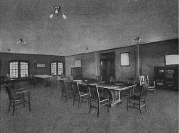
One of the most interesting features of this part of the work is the assembly and reading room, which is accessible to those who may be off duty. A view of the interior of this room is shown in Fig. 16. It is fitted up with comfortable furniture which harmonizes well with the finish of the room. Large tables are provided, where the current technical literature is obtainable for those who desire to read. Well-filled bookcases stand along the wall, and their contents form part of the circulating library which the Chicago Edison and Commonwealth companies keep up for the benefit of those in their employment.
Boiler-house employes have quarters located directly above the north boiler unit. Here are provided well-ventilated locker rooms, lavatories, shower baths, etc. In these quarters is also located the office of the boiler-house engineer, who is thus at all times in close communication with the men of his department.
The turbine-house employes have their quarters on the second floor of the switch house, where they have their own locker and bath rooms.
Miscellaneous Features.
To furnish excitation to the generators in case of emergency a storage battery has been provided, of the Electric Storage Battery Company's make, situated in the third story of the main station building. The battery contains 70 type G cells and is provided with the usual end-cell regulation, the end-cell switches being contained in a separate room.
The West Twenty-second Street Substation, which is located on the Fisk street property, is now in course of construction. It contains one 1,000 and one 500 kilowatt motor generators, which transform the incoming current from 25 cycles to 60 cycles for distribution. There is also a 2,000-volt rotary converter which supplies current to the station and for adjacent territory.
In order that better transit facilities be provided between the Fisk Street Station and the Harrison Street Station and downtown offices than is afforded by the street railway lines, the officers of the company have for their use an electric launch, which will take them by water between these points in a few minutes. The launch is one of those used at the Pan-American Exposition, and will seat 20 people. It is provided with 44 Chloride accumulator cells with 120 ampere-hour capacity, and may be propelled at five different speeds by a six-horse-power 88-volt motor.
Among the contributors to the success of this work should be mentioned Sargent & Lundy of Chicago, who were the consulting engineers; Shepley, Rutan & Coolidge of Chicago, the architects who designed the group of buildings, and the gentlemen composing the Commonwealth company's permanent engineering staff, under whose supervision the apparatus was installed. The result is an electric-light and power station, which, already one of the most notable in the country, is to be extended to be, perhaps, the largest in the world.
