[Trade Journal]
Publication: Western Electrician
Chicago, IL, United States
vol. 30, no. 13, p. 205-207, col. 1-3,1-2
Independent Electric Plant in San
Francisco.
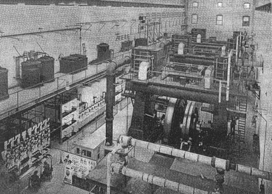
The plant of the Independent Electric Light and Power company of' San Francisco, which has recently been completed, contains many interesting engineering features. The electrical system supplied by the company is an alternating-current one, the current being generated by two-phase alternators, transmitted to sub-stations by three-phase circuits and distributed by means of two-phase alternating and three-wire direct current. Constant-current and constant-potential alternating circuits are also supplied for arc lighting. In the main power station four steam-driven units are used to apply the necessary power. A general view of the engine room of this station is shown in Fig. 1.
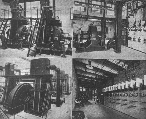
Of the four generating units, three consist of 1,500-kilowatt, engine-type alternators, directly connected to cross-compound vertical engines and one 500-kilowatt alternator, similarly driven. One of the larger units is shown in. Fig. 8 (page 207). These generators deliver a two-phase current at 500 volts and 7,200 alternations. The 1,500-kilowatt machines run at a speed of 116 revolutions per minute and have 62 poles. They have rotary armatures, the rotating member being built up on a cast spider and pressed on the engine shaft. The external frame is divided in a vertical plane, so that it may be moved away from the shaft to allow access to the windings. The separately excited field requires 250 amperes at 100 volts. A load of 1,500 amperes per terminal at 500 volts may be thrown off, and the electromotive force is guaranteed not to rise more than six per cent. with constant speed and constant separate excitation. The full-load efficiency of each generator is 95 per cent. The temperature rise for 24 hours at full load does not exceed 40 degrees Centigrade, and at 50 per cent. overload for one hour the rise in temperature does not exceed 60 degrees. The pole pieces of the field are of laminated steel and are so proportioned as to reduce the armature reaction and self-induction to a low limit. The field coils are wound with strap copper on edge and permit good air circulation. The armature is of the slotted-drum type, and is built up of laminations held together between end plates.
The 500-kilowatt alternator runs at 157 revolutions per minute, and with 46 poles gives 7,200 alternations at 500 volts. The field is horizontally divided and the rotating armature has bar-wound coils. The machine operates in multiple with the 1,500-kilowatt machines.
For exciting purposes two 100-kilowatt, engine-type, 125-volt generators are installed. These generators are compound-wound and are directly connected to vertical piston-valve engines of the center-crank, high-speed type. The exciter units are illustrated in Fig. 6. Each exciter is provided with an ammeter, voltmeter, Bristol recording voltmeter, rheostat, circuit-breaker, and two three-pole switches, by which the exciter may be connected to either or both sets of bus-bars. Between the direct-current bus-bars in each generator field are two sets of switches for connecting the fields to either or both sets of the bus-bars, also one ammeter and one generator rheostat.
The two-phase, 500-volt current from the generators is raised to 10,000 volts, three-phase, by means of six 750-kilowatt static transformers and then passes to a transfer station, and thence to three sub-stations, from which distribution by alternating current is made at 2,200 volts, two-phase, and by direct current at 220 volts from the rotary converters.
Between each alternator and the set of raising transformers which it supplies are two alternating-current voltmeters, one Bristol recording voltmeter, two circuit-breakers with time relay, one four-pole switch, two integrating wattmeters, two indicating wattmeters, and two Bristol recording wattmeters. There is also provided a single-pole switch for connecting the generators to a set of bus-bars used for holding the machines in multiple, by switching on the high-tension side.
| |||
| Fig. 1. Independent Electric Plant in San Francisco. General View of Engine Room. |
Between the raising transformers and the high-tension bus-bars there are for each set of transformers three single-pole switches for connecting to the first set of bus-bars, three single-pole switches for connecting to the second set, and three single-pole switches for connecting to the outgoing feeder.
There are six jaw switches connecting the bus-bars, which receive current from the machines to the bus-bars that supply the outgoing feeders. The current capacity of these switches is 300 amperes. Between each wire of each feeder and one bus-bar of each of the two sets there is a single-pole switch, making a total of 24 single-pole jaw switches, each with a current capacity of 130 amperes. For each feeder there is one double-pole, high-tension circuit-breaker, with time-element attachment. Each feeder is also provided with three ammeters of 200 amperes' capacity each, and, in addition, there are the necessary synchronizing switches. The high and low-tension switchboards in the main power house which contain these switching appliances are shown in Fig. 2. The rear of the 10,000-volt, high-tension board is illustrated in Fig. 3, while Fig. 4 shows the rear of the low-tension alternating-current switchboard.
The transfer station receives four high-tension circuits from the power station, and from it two high-tension circuits run to each of the three sub-stations. For making connection between the four incoming feeders and the six outgoing feeders, there are provided 36 single-pole jaw switches, each having a current capacity of 150 amperes. These switches are mounted on the switchboard shown at the right in Fig. 5.
In sub-station "A" there are three sets of lowering transformers. Each set consists of two transformers of 400-kilowatt capacity, and receives three-phase current at 10,000 volts, delivering two-phase current at 2,000 volts. The equipment also includes two rotary converters of 250 kilowatts' capacity and four static transformers for supplying the same, of 150 kilowatts' capacity each. The instruments in this sub-station are as follows: Each set of two lowering transformers is supplied with six single-pole, high-tension fuse circuit-breakers for connection to either of the two incoming three-wire feeders. Between the secondaries of each set of lowering transformers and the 3,000-volt bus-bars are mounted one ammeter for each transformer, two circuit-breakers and two double-pole, double-throw switches (the latter for connecting transformer secondaries to either of two sets of four-wire bus-bars). For each set of bus-bars there is one voltmeter, with proper plug and receptacles, so that it may be connected to either of the two phases. Provision is made for four outgoing two-phase, four-wire feeders, with the necessary double-throw switches, so that each feeder may be connected to either set of 3,000-volt bus-bars. Each feeder is provided with two ammeters and two single-pole circuit-breakers. The four 150-kilowatt lowering transformers which supply current to the rotary converters are provided with six high-tension fuse switches for connecting the transformers to either incoming feeder. Between the lowering transformers and the rotary converters are two ammeters and one four-pole switch. Between the direct-current terminals of the rotary converter and the bus-bars there is a voltmeter, circuit-breaker, double-pole switch and ammeter. In connection with this apparatus there is also one direct-current field ammeter and one four-pole switch for starting the motor, together with necessary synchronizing apparatus. The rotary converter is provided with a Hartford regulator with series converters for changing the electromotive force supplied to the rotary converter, so that the direct-current voltage may be varied from 220 to 300 volts. There is provision for two two-wire, 220-volt, direct-current feeders, each provided with a 500-ampere circuit-breaker, ammeter and double-pole switch.
The apparatus in each of the other two sub-stations is a duplicate of that described for sub-station "A," except as to size. One of these sub-stations, which contains three rotaries, is shown in Fig. 9, and the other one, containing but one rotary, is illustrated in Fig. 7. The rotaries are all started by 15-horsepower induction motors, designed to receive two-phase current at 180 volts. The efficiency of the 250-kilowatt rotaries is guaranteed to be 92 per cent. on full load, and they deliver direct current at any voltage between 220 and 300 volts.
For lightning protection there are provided six units of the Westinghouse type-R lightning arrester, designed to protect both ends of the three-wire, 11,000-volt circuit. For the direct-current circuits there are provided four type-L single-pole line lightning arresters. The efficiency of the 750-kilowatt raising transformers is 98.35 per cent. and the temperature rise with continued full load is guaranteed not to exceed 45 degrees Centigrade. The efficiency of the 250-kilowatt lowering transformers is 98 per cent.
The boiler equipment at the main power house consists of 12 625-horsepower water-tube boilers of the Babcock & Wilcox type. Each boiler is equivalent in capacity to five return tubular boilers six feet in diameter and 16 feet long. They are constructed of forged steel throughout and are built to carry a safe working pressure of 200 pounds. The boilers are arranged in batteries of two each. The proximity of the power house to the California oil fields has made it economical to use oil as fuel and each boiler is provided with three oil burners.
 |
| (Left Top) Fig. L. High and Low-Tension Switchboards in Power Plant. (Right Top) Fig. 3. Rear of 10,000-Volt Switchboard. (Left Bottom) Fig. 4. Rear of Low-Tension Switchboard. (Right Bottom) Fig. 5. Switchboards at Transfer Station Independent Electric Plant in San Francisco. |
The engines, which have been already mentioned were built by Mclntosh, Seymour & Co. The three larger engines have cylinders 28 and 58 inches in diameter by 48 inches stroke, and at 165 pounds steam, condensing, and 116 revolutions per minute, are rated at 2,400 indicated horsepower. The fourth main engine has cylinders 17 and 36 inches in diameter by 30 inches stroke, and at 160 revolutions per minute is rated at 760 indicated horsepower. Each engine is provided with a complete oiling system. The governors, of the centrifugal-shaft type, are each equipped with a speed-changing device driven by a small electric motor mounted on the governor weight. All the engines exhaust into a Wheeler surface condenser.
| |||
| (Left Top) Fig. 6. Exciter Units in Main Power House. (Right Top) Fig. 7. Single-Rotary Sub-Station. (Left Bottom) Fig. 8. Unit of 1500 Kilowatts. (Right Bottom) Fig. 9. Three-Rotary Sub-Station Independent Electric Plant in San Francisco. |
The power house is located on San Francisco Bay, and all the circuits are underground, except the high-tension circuits, which are carried by a pole line to the sub-station of the San Francisco and San Mateo Electric Railway company, a distance of over four miles, and the distribution lines of the residence district. For these distribution lines there are provided 35 manhole transformers of 50 kilowatts' capacity each, 2,200 volts' primary and 220 or 110 volts on the secondary; also 14 of 25 kilowatts' capacity and 10 of 10 kilowatts. All of the manhole transformers are to have leads brought out, so that they may be connected to transfer from 2,300, 2,166, 2,133 or 2,100 volts to 222 and 110.
All of the electrical equipment of the main power house and of the sub-stations was supplied by the Westinghouse Electric and Manufacturing company of Pittsburg, Pa. This company also furnished the street transformers mentioned above. The entire plant was erected under the supervision of A. M. Hunt, the manager of the Independent company.
