[Trade Journal]
Publication: Western Electrician
Chicago, IL, United States
vol. 30, no. 20, p. 341-342, col. 3,1-2
Central-station Current Used for
Elevated-railway Operation.
An important engineering work has just been completed by the Lake Street Elevated Railroad Company of Chicago, by which the power-supply facilities of that company's line are considerably increased. The work comprises a sub-station, containing transformers and rotary converters, receiving high-tension, alternating current and delivering, direct current at 550 volts to the third-rail feeders on the elevated structure. The sub-station is located at Rockwell and Lake Streets, where an old building that at one time contained an .electric-lighting, plant for lighting the .stations of the road has been changed so as to make it suitable for rotary-converter purposes. The current for operating the sub-station is obtained under contract from the Chicago Edison Company and is carried underground from that company's Harrison Street station at a pressure of 9,000 volts by means of three No. 0000 wire, enclosed in a lead-covered cable. The distance of transmission is about 3 1/2 miles.
The three 9,000-volt cables enter the sub-station building at one corner of the basement and are connected to high-tension bus-bars under the oil switches. These bus-bars consist of three 2,500,000 circular-mil cables, covered with nine-thirty-seconds-inch insulation and supported on triple-petticoat glass insulators. Between two of the bus-bars is connected a potential transformer, reducing the voltage from 9,000 to no volts, for use in connection with the alternating-current voltmeter and synchronizer on the alternating switchboard. From the high-tension bus-bars two three-phase circuits lead to the oil switches directly above on the main floor of the substation. These switches are of the double-break type, and are mounted in brick compartments. Each switch is operated by a one-horsepower, 110-volt, direct-current motor, supplied from a small storage battery, in order to provide certainty of operation. The battery consists of 55 two-plate cells and is located in one corner of the basement.
| |||
| Fig. 1. Central-Station Current Used for Elevated-Railway Operation. Transformers and Rotary Converters at Lake Street Sub-Station. |
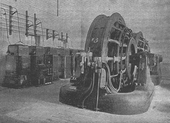
From the oil switches the high-tension current is carried to the static transformers, shown at the left in Fig. 1, on six No. 00 cables, wound with eight-thirty-seconds-inch insulation and supported on double-petticoat glass insulators. The transformers are six in number and have a capacity of 375 kilowatts each. They step down the current to 430 volts alternating, each set of three supplying one of the rotary converters (shown at the right in Fig. 1) with a six-phase current through 1,300,000-circular-mil cables. The rotaries are diametrically connected, there being about 350 volts between the collecting rings. The transformers are air-cooled by means of two blowing sets. Each set consists of a blower, driven by a five-horsepower induction motor. The transformers are set on a steel floor, supported by an I-beam construction and connected to a common ground. It is customary to start the rotaries from the direct-current side, but, when necessary, they may be started from the alternating side by means of two 1,200-ampere, triple-pole, double-throw switches, mounted in front of the transformers. One of these switches is shown in Fig. 1. By throwing the switch up, a starting current of 143 volts is supplied. In normal operation the switch is kept on the lower contacts.
The rotary converters, which are about the largest machines of the kind in the West, supply a direct current of 600 volts. As the equalizer is connected to the negative conductors, each rotary is provided with a switch, by which the equalizer can be grounded for starting the rotary, so that the starting current will not go through the series winding, which would necessitate a heavy starting current. The negative conductors, two from each rotary, are carried out of the building and connected to the elevated structure. The positive conductors are run through the basement to the direct-current switchboard, which is shown at the right in Fig, 2.
This switchboard is built of black-marble panels mounted on an angle-iron framework. At present it contains six full panels, and room is provided for four additional panels when the capacity of the plant is increased. The two rotary panels are shown at the right of the board. On each panel is mounted an 8,000-ampere, latest-type circuit breaker, an astatic ammeter, a main single-pole, single-throw starting switch, a double-throw lighting switch for the station lighting and a Thomson recording wattmeter. The field and starting rheostats are located in the basement, directly beneath, and are controlled from the board, the former mechanically by rods and chains and the latter electrically by copper wires.
The rotary panels feed into a common bus on the back of the board, and from that are connected two feeder panels and what is called an auxiliary feeder panel. Each feeder panel is provided with a circuit-breaker, astatic ammeter and main switch as well as an auxiliary switch. The auxiliary panel has a similar equipment, but with only one switch. It is connected to an auxiliary bus-bar and is designed to be thrown on either feeder panel in case a circuit-breaker is burned out or it is desired to make repairs to any of the instruments. When the auxiliary panel is in use the current goes through the main feeder and auxiliary switches on the feeder panel and then through the whole of the auxiliary panel, leaving the main circuit-breaker and ammeter dead.
| |||
| Fig. 2. Central-Station Current Used for Elevated-Railway Operation. Alternating and Direct-Current Switchboards at Sub-Station. |
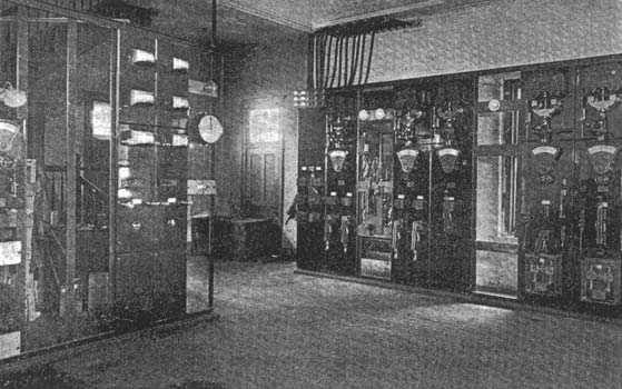
The last panel on the left of the main switch-board is a transfer panel and is equipped with two single-pole, double-throw, 4,000-ampere switches for switching current from either the sub-station or the Western Avenue power house of the Chicago Union Traction company (from which power is now rented) onto the feeder sections. There are two sections that are thus controlled. Section 3 extends from Campbell Avenue to Fifty-second Avenue, and section 2 from Campbell Avenue to the Chicago River. At present the rotaries help out the Western Avenue power for both sections, but eventually, when the capacity of the sub-station is doubled, as has already been planned, all the power for the two sections will be supplied from the sub-station. Temporarily installed in one of the spaces left for a future panel is a circuit-breaker that is used in starting the rotaries on the direct-current side. Its capacity is smaller than that of the larger ones and is used to save the latter. At the right end of the board is mounted a voltmeter for registering either the voltage of the machines or the line voltage.
The switchboard shown at the left in Fig. 2 controls the oil switches and storage battery and has the alternating-current instruments mounted upon it. The small panel at the extreme left has an astatic voltmeter and two switches for the oil-switch motors. The storage battery is charged from the 550-volt direct-current circuit, three circuits, each of four incandescent lamps in series, being used as resistance instead of a rheostat. These lamps are located in the basement and also supply the necessary illumination for that part of the building.
 |
| Fig. 3. Central-Station Current Used for Elevated-Railway Operation. Sub-Station Wiring Diagram. |
The two alternating-current panels are each equipped with a voltmeter, ammeter and power-factor indicator, the potential used being 110 volts. This is obtained from the 430~volt mains by potential transformers in the basement. At the right of the board is mounted a Lincoln synchronizer which is used to throw the rotaries into parallel operation. In Fig. 3 is shown a wiring diagram of the sub-station, which is complete, except that only one rotary panel, one oil switch and one alternating instrument panel are indicated.
The new sub-station was put into service on April 26th and has proved itself of great assistance to the operation of the road. All the electrical apparatus used in the installation is of the General Electric Company's manufacture. The reconstruction of the building and the design and installation of the equipment were executed under the supervision of Augustus Hanson, electrical engineer for the Lake Street and Northwestern Elevated companies.
