[Trade Journal]
Publication: Western Electrician
Chicago, IL, United States
vol. 33, no. 15, p. 270-272, col. 1-3
Overhead Pole-line Construction and Operation for Central Stations.(1)
By A. H. Manwaring and J. T. Hutchings.
This paper treats of some of the important points to be considered in successful pole-line construction for a plant supplying current for series arc lighting and alternating current for light and power, and refers especially to the methods in vogue in those sections of Philadelphia where business at the present time is not sufficient to warrant the installation of underground wires. Poles.
The poles most frequently used are chestnut, south- ern cedar, pine and iron. Chestnut poles, when well seasoned, are preferable for general line use, and are purchased to conform to the following specifications: The poles must be straight, live white chestnut, having all bark removed and knots trimmed flush with the surface. The poles must not be less than 8-1/2 inches in diameter at the top and have the following dimensions six feet from the butt: Thirty-five-foot poles, 13 inches diameter; 40-foot poles, 14 inches diameter; 45-foot poles, 15 inches diameter; 50-foot poles, 16 inches diameter; 55-foot poles, 17 inches diameter; 60-foot poles, 18 inches diameter.
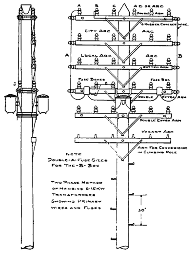
The poles should be well shaved with a draw-knife, except the part to enter the ground, which varies in length from five to seven feet. Poles are roofed at the top to form a right angle. The poles are "gained" to form a flat of about five inches for the attachment of the cross-arms, which are spaced 24 inches between centers, the top of the first arm being one foot from the top of the pole.
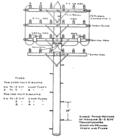 |
| Fig. 1. Overhead Pole-Line Construction. |
All poles upon which are located devices requiring regular inspection, should be provided with steps in order to facilitate this work. The standard step is made of galvanized iron, one-half-inch diameter by nine inches long, having three inches of thread. These are preferably placed 15 inches apart, the distance between the two steps on the same side of the pole being 30 inches, and the first step is placed six feet from the ground.
Poles are spaced from 40 to 45 yards apart, de- pending on circumstances, and all end and corner poles are guyed with one-quarter-inch or three-eighths-inch stranded galvanized wire. In long lines every tenth pole is also guyed, the wire being carried from the top of one pole to about six feet from the base of the next. Poles are periodically inspected to determine if they are in good condition and perfectly safe.
Iron poles, generally speaking, should be avoided on account of the liability of shock to the linemen when working on live wires. The use of these poles, however, cannot always be dispensed with, and when used for street arc lighting, the lamp should be so arranged that it can be lowered and trimmed from a step ladder, thus protecting the trimmer. If it is found necessary to suspend the lamp from a bracket attached directly to an iron pole, thus necessitating trimming from the pole itself, a portable grounding wire should be furnished which can be attached to the lamp, thus grounding the circuit and making it perfectly safe for the trimmer. This arrangement has been found to work very satisfactorily in actual service, although some trouble has been caused by the trimmer neglecting to remove the grounding wire after trimming the lamp. This, however, has been overcome by imposing a nominal fine for each offense. The safety of the trimmers is also considerably increased by grounding both wires of the circuit in the station during the time that the current is off, Poles of southern cedar lack mechanical strength, and nine is short-lived. These poles are, therefore, inferior to chestnut and should not be used when the latter is obtainable.
Junction Poles.
Junction poles in the past have caused considerable trouble, principally due to the manner in which branch lines, at right angles to the main line were connected, and, further, to the placing of fuse boxes on these poles. It is of the utmost importance that the wiring of junction poles should be made as simple as possible. Branch wires should be attached to reverse arms, and the connections from the main to the branch circuit be made by vertical taps. Under these conditions, the junction pole will be safe and accessible to linemen.
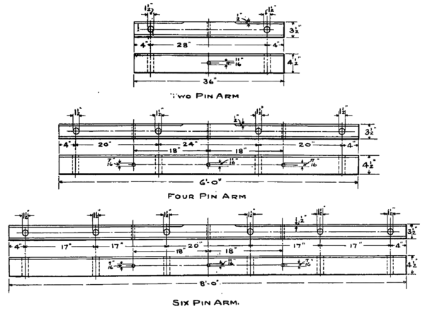
Cross-arms.
Cross-arms should be made of selected yellow pine, free from knots and sap, finished on all four sides and having the upper corners chamfered, except where the arm bears against the pole. Cross-arms should always be purchased unpainted in order to permit of rigid inspection, and immediately upon acceptance they should be covered with three coats of good white lead and oil.
Figs. 1 to 6 show the dimensions, of the cross-arms.
Cross-arms are attached to the poles with five-eighths-inch through bolts with nuts and washers.
Braces.
The braces are made of galvanized iron 28 inches long, 1-1/4 inches wide, three-sixteenths inch thick, having a hole two inches from each end, one seven-sixteenths inch and the other nine-sixteenths inch in diameter. Carriage bolts, three-eighths inch by four inches are used for attaching the braces to the cross-arms, and one-half by four-inch lag screws for attaching them to the poles.
Pins.
Locust pins 1-1/2 by nine inches, well boiled in linseed oil, are preferable for lines of 5,000 volts and under.
Insulators.
Double-petticoat glass insulators are used for all series arc wires and secondary distributing wires. For alternating-current lines of 2,000 volts and over, a special porcelain insulator is used in Philadelphia.
Lightning Arresters.
Lightning arresters are required primarily for the protection of transformers on the line and of apparatus in the station. The arrester installation for the station should be the best obtainable, and should be so placed as to be under continual supervision by the switchboard attendant. With the exception of these, no lightning arresters should be placed on the main line.
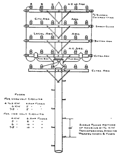 |
| Fig. 2. Overhead Pole-Line Construction. |
Each branch line should be protected with at least one set of lightning arresters, and in some instances several should be used, depending on the length of the branch line, location of the transformers, and the nature of the territory covered. All lightning arresters should be carefully grounded, and it should be borne in mind that one set of arresters properly installed is superior to a number of arresters with poor ground connections.
Lightning arresters should not be directly protected by fuses, but they should be arranged with suitable devices to easily cut them out of circuit for inspection. This can be accomplished by the use of suit- able fuse boxes having copper wire substituted in place of the fuses, or line switches having carrying capacities equal to that of the lines. After every heavy electrical storm, lightning arresters should be inspected to see that they are not damaged, and periodic inspections should be regularly made to see that the gaps are clear from dirt of dust.
Fuse Boxes.
The following are a few of the necessary requirements of a satisfactory fuse box on alternating-cur- rent circuits having voltages of from 2,200 to 2,500 volts:
First The fuse should be capable of opening the circuit under any and all conditions of short-circuit or overload. Second The fuse box should be designed to prevent any leakage of current from the metal parts in circuit to the case of the box, under any and all conditions of weather. In fact, the insulation should be such that the box would operate with perfect satisfaction if mounted upon an iron cross-arm. Third the break distance should be sufficient to allow of the opening of the box under an inductive load of at least 30 amperes, without causing trouble. Fourth The box should be arranged to be easily and securely attached to standard cross-arms in such a position as to be easily and safely opened for inspection and for the replacing of fuses. Fifth The box should be so arranged for the introduction of wires as to render contact with them unnecessary when the linemen open the box. Sixth The design should be such that when a fuse is replaced the lineman is in no danger of being burned by the arc or hot metal, or of receiving an electric shock.
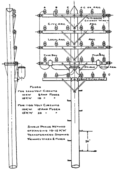 |
| Fig. 3. Overhead Pole-Line Construction. |
At the present time there is no fuse box on the market that entirely meets all of these requirements, although several fulfill many of them. Fuses which were formerly perfectly satisfactory on 2,200-volt circuits, supplied by small generators, operated singly, will no longer break the circuit in case of short-circuit on the larger generators now generally used. When short-circuits occurred under the old system, the engines slowed down and the generator voltage dropped practically to zero, and almost any of the fuse devices on the market would open the circuit. At present large generating units frequently operate in parallel, and a fuse to be satisfactory should be capable of being blown directly across the bus bars at the station without maintaining an arc. In Philadelphia we have instituted a rule to install no fuses of a greater capacity than 30 amperes on our alternating-current distributing lines. With a circuit-breaker at the station set for 125 amperes, these fuses will then open the branch circuit with little or no- indication at the station.
The cut-outs protecting transformers, should be so located as to be easily and safely reached for inspecting and replacing fuses. The connecting wires to the fuse boxes should be insulated with at least five thirty-seconds-inch rubber, covered with a double saturated braid, and secured in such a manner that it is impossible for them to come in contact with other lines.
Location and Installation of Transformers on Pole Line.
Transformers should be attached to cross-arms entirely independent of those carrying high-tension lines and should be so located as to be easily inspected. If the transformers are of large sizes, the arms to which they are attached should be rein- forced in such manner as to insure their security under all conditions, and if necessary an additional arm should be placed below them to facilitate the climbing of the linemen to the upper part of the pole. Under no condition should the transformer lie erected in such a position on the pole as to interfere with the regular work of the linemen.
Location and Construction of Main or Trunk Lines.
The territory to be supplied should be divided into sections having as far as possible definite boundaries, both for series arc and alternating-current circuits, in order that the power house, switchboard and line attendants and the office force also may be conversant with the exact district covered by each circuit.
The number of wires leading from the power house should be reduced to the least possible number. This can be be.st accomplished by increasing the size of the circuits and operating at high voltages. For this reason and also for the betterment of the service, all 1,000-volt alternating-current circuits should be increased to 2,000 volts, and series arc circuits to 125 lights each. With such a system the number of wires leading from any station can be kept within satisfactory limits. There should be, however, not less than two main trunk lines leading from the power house, and these should be run in as direct a line as possible to the centers of the various sections. However, care should be exercised that these lines are run in streets having the least number of telegraph and telephone wires, and also where they will be least objectionable to the public. In fact, it is preferable to increase the length of a line 1,000 or even 2.000 feet than to select a more direct route at the expense of public good will.
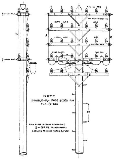 |
| Fig. 4. Overhead Pole-Line Construction. |
Series circuits for both arc and incandescent street lighting should, as far as possible, be laid out in compact blocks, and so arranged that with the exception of the main lines there will be but one line on a street; in other words, a circuit should run out on one street and return on another.
Each series arc circuit of 125 lamps should be subdivided into at least three loops, so arranged that anyone can be separately cut out by a switch, this will be found of great assistance in locating open circuits and grounds; and in case of fire, the section affected can be easily and safely cut out without interfering with the rest of the circuit.
All wires on the main or trunk lines should be well drawn up in order to prevent crosses. All series circuits from the power house to the point where the circuit branches should be carried on pins occupying the same relative positions counting from the top of the pole. This would also apply to alternating-current circuits, unless the distances covered are such as to require transposition. No cut-out boxes, transformers or lightning arresters should be erected upon the main or trunk lines as previously mentioned. The wires for the circuits which first branch off from the main line should be carried on the lower cross-arms, and wires supplying the more distant sections should be carried above; the reason being, that wires which require least attention should be placed out of the way of the linemen, whose services are generally most needed on those wires which supply the business in the immediate neighborhood.
 |
| Fig. 5. Overhead Pole-Line Construction. |
Where series arc or series incandescent lines for street lighting are erected on the same poles with alternating-current lines, they should be carried below the latter since theyre out of circuit during the day; in other words, all high-tension lines which are in circuit continuously, should be located on the top cross-arms, thus obviating the necessity of linemen when working on the series lines from coming in contact with them. For the same reason, the secondary lines being safely handled, should preferably be placed on the lower arms. Secondary wires should not be attached to the same cross-arms with high-tension lines, unless on opposite sides of the pole.
It is advantageous to erect alternating-current lines which are in circuit 24 hours daily, on a distinct type of insulator, in order that linemen well know at a glance what circuits are alive. This can readily be accomplished by using porcelain insulators for alternating-current and glass insulators for series circuits, the latter being in use only at night. This is also of assistance in tracing out the circuits.
All branch circuits should lead from reverse arms, except in the case of single series arc loops which may be attached to an iron break-arm on the outside or end pin. If alternating-current branch circuits lead in both directions at cross streets, the wires should be carried straight across and a common connection made to the main line.
The necessary fuse boxes to protect the mains should be placed on the first pole each side of the trunk line.
Where numerous telephone or telegraph wires cross above electric-light wires, a separate six-pin cross-arm should be attached at the top of the pole for supporting two No. 10 galvanized iron wires (one at each end of the cross-arm) stretched from pole to pole as guard wires.
Grounding of Secondaries.
All secondary mains supplied by transformers should have the neutral wire of the three-wire system or one wire of the two-wire system grounded. It is also necessary that a suitable ground be furnished at the premises of each consumer, in addition to the regular installed grounds upon the system. In case of a number of transformers being connected in multiple there should be a ground for each transformer.
 |
| Fig. 6. Overhead Pole-Line Construction. |
It might be mentioned incidentally that in connecting two-wire meters the field coils of the meter must not be connected to the grounded side of the system, as otherwise there may be a loss of revenue, due to the meter being shunted by grounds in the building, etc. When conducting a periodic test of the meters, the condition of the ground connections in the building should be examined and repaired if defective.
Complaints.
We have found it quite advantageous to have certain of the regular day force of linemen detailed alternately to look after the complaints at night. Each man naturally gives more attention to the character of his work when he appreciates that his duties when on the night shift, are more or less arduous in proportion to the manner in which he and his companions have performed their work during the day.
Rules.
If the plant is of sufficient size to require division into sections or districts for successful operation, a uniform system of rules and diagrams should be used in order that all work of the same character shall be performed in a uniform manner. This enables a lineman to be transferred from one di vision to another, and still be perfectly familiar with his work.
The following are a few of the general rules to line foremen:
1. No wire of smaller size than No. 6 B. & S. gauge shall be used for either primary or secondary work.
2. All alternating-current primary line wire shall be erected on porcelain insulators upon adjacent pins.
3. All arc-line wire shall be erected on double petticoat glass insulators.
4. Alternating-current and arc line wires shall in no case be placed upon the same cross-arm unless the pole is between.
5. All joints shall be well soldered and taped.
6. Secondary lines shall at all points be at least 18 inches from primary or arc lines unless covered with heavy porcelain tubes.
7. Fuse boxes shall be placed upon all branch circuits.
8. The main circuits shall not be fused as long as the wires are maintained of the same size as at the station.
9. Fuse boxes for branch circuits shall in all cases be fused 25 per cent, smaller than the main fuse at switchboard; and in no case shall branch fuse boxes be fused with copper wire.
10. Fuse boxes for branch circuits shall be placed upon the first pole from the junction pole.
11. Transformers shall not be placed on the exterior of buildings, sheds or other property belonging to the consumer.
12. All poles having transformers or fuse boxes upon them shall be stepped.
13. No fuse box or transformer shall be placed upon a junction pole or lamp pole, except where absolutely necessary, in which case the office shall be notified and permission obtained.
14. Transformers shall be placed upon poles practically as shown in diagrams [Figs, 1, 2, 3, 4 and 5], and in all cases full six-pin arms shall be used.
15. In placing transformers for motors, one kilo- watt should be allowed for each horsepower up to 30 horsepower, except where a number of motors are installed upon one group of transformers, in which case, the capacity may be reduced in accordance with the condition of load.
16. All consumers having 200 lights or over, who are not regular in their hours of burning, such as churches, lodge rooms, public halls, etc., shall be placed upon two-phase wherever possible.
17. In connecting two-wire consumers upon three- wire secondary circuits, care should be taken that the of burning load is evenly balanced, as to location and time
18. Wherever practicable, consumers should be grouped upon one transformer, or system of transformers and secondary wires.
19. The object in grounding a secondary wire of transformers is to prevent high-tension current from reaching the secondary wires. The neutral wire of all three-wire secondary circuits must be grounded, and also one side of all two-wire secondary circuits.
20. It is of the utmost importance that the primary fuses protecting each transformer shall be of a size proportionate to the capacity of the transformer. When a transformer is fused excessively heavy, or with fuses of dissimilar sizes, one fuse only is liable to blow, thus leaving current on the defective transformer.
21. It is essential that, when a primary fuse on the transformer is blown through any cause, the secondaries should be disconnected from the transformer and the latter tested to full line voltage between the primary and secondary coils, so as to determine that there is no breakdown in the insulation between these coils.
22. All alternating-current circuits should lie tested daily for grounds.
23. All series lighting circuits should be tested for grounds within 10 minutes after the circuits are taken off, and for open circuits, crosses and grounds at 12:10 p. m. and 3:10 p. m., and also one hour before starting time.
(1) A paper (somewhat abridged) read before the Association of Edison Illuminating Companies at the Thousand Islands, near Clayton, N. Y., on September 8, 1903, The authors are connected with the Philadelphia Electric Company.
