[Trade Journal]
Publication: Western Electrician
Chicago, IL, United States
vol. 34, no. 1, p. 6-9, col. 1-3
Arnold Single-phase Electropneumatic
Railway System.
To the Editor of the Western Electrician:
As many of your readers know, I have persistently advocated the use of the alternating current directly in the motors for electric railways for several years (See Transactions American Institute of Electrical Engineers, joint meeting with the British Institution of Electrical Engineers, Paris, August 16, 1900; Niagara Falls convention, August 24, 1901; Great Barrington, Mass., June 19, 1902, and New York, September 26, 1902). By referring to the discussions which took place at these meetings and to the technical journals, it will be found that there were few, if any, other advocates, in this country, of the alternating-current motor for railway work until recently, and that those who supported it abroad advocated the use of three-phase currents until within the last few months. Since my announcement of the principles of my system before the Great Barrington convention the development of the single-phase alternating-current railway motor has been remarkable, both in this country and abroad, and while at that time it had few friends, the development has been such since that it now seems destined to take its place as the leading railway motor, thereby effecting a revolution in electric-railway work.
Many of your readers also know that, since announcing the principles of my system before the Great Barrington convention, I have refrained from giving out any further information regarding it giving as my reasons therefor my desire to test the system thoroughly before making further public statements regarding it, and then to present a full and complete description of it, together with the results of its operation in the form of a paper before the American Institute of Electrical Engineers. Consistently pursuing that policy, I have conducted my experiments privately and at my own expense, and had so perfected my apparatus that I had hoped to be able to celebrate the incoming of the year 1904 with a public demonstration over 20 miles of railroad, which would conclusively prove that the single-phase electric railway is not only operative but efficient and less in first cost and operation than any system now in vogue, not meaning to imply thereby that the system which I have developed was necessarily the only system or the best system, for only time can prove the correctness or, incorrectness of such statements, but that it was a system which would successfully do the work, and the system which was first developed and first to be put in actual operation upon the first electric railway in the world especially built for single-phase alternating-current motor operation.
 |
| Fig. 1. Arnold Single-Phase System. Special Insulator. |
That I would have made a demonstration on January 1st was a certainty to me until December 18th, when I learned by telegraph, while in New York that the car barns located at Lansing, Mich., of the road upon which I had been experimenting were completely consumed by fire at four o'clock that morning. The fire apparently originated from a stove in the engine house and was communicated so rapidly to the car barns that it destroyed a steam locomotive and two new cars built for my system as well as my experimental locomotive, thus leaving me unable to make the demonstration as I had planned. In view of the fact, however, that the single-phase electric railway is now receiving so much attention at the hands of engineers and inventors in many parts of the world, and that I believe that the year 1904 will be an epoch-making one, marking the revolution from the direct-current to the alternating-current motor for railway work as well as the beginning, on a large scale, of the displacement of the steam locomotive on railways by the use of a substantial form of overhead construction rather than the third rail, and from the further fact that I cannot get another machine ready in the near future, I have concluded that I will give to the technical press a record of my work up to the present time, in order that that work and the system which I have developed may be properly weighed in comparison with the work and systems of others, leaving the more complete description of the system and the results of its operation to be presented at a later date before the American Institute of Electrical Engineers.
 |
| Fig. 2. Arnold Single-Phase Railway System. Overhead Construction. |
On January 10, 1900, I rode over the country between Lansing and St. Louis, Mich., a distance of about 60 miles, with a party of gentlemen who desired to build an electric road between these points. This trip resulted in my advising them that the territory was such that I believed the road should be built as economically as possible, and inasmuch as they desired me to assist financially in its construction, I told them I would do so provided I was allowed to construct the road in accordance with certain ideas that I then had in mind, for by such construction the first cost of the road could be kept sufficiently low to warrant its construction, and that if it were built on any one of the systems standard at that time the advisability of building it was questionable. The result was that on April 23, 1900, a contract was entered into wherein I undertook to build and equip the road. Engineers were at once placed in the field to locate it, and after the plans were sufficiently completed the grading, bridging and track work of 20 miles of the road followed, and this much of the road was completed to such an extent that steam trains were put in regular operation over it about November 15, 1901.
 |
| Fig. 3. Arnold Single-Phase System. Diagramatic Arrangement of Electropneumatic Motor. |
For financial reasons the completion of the road was delayed, and in the meantime the development of my system was taking place and the parts being perfected in different offices and shops.
Since it was my intention to experiment with pressure as high as 15,000 volts on the working conductor, all of the line material had to be specially designed, but the work progressed to such an extent that the overhead and line work of 20 miles of road was practically completed and ready, for operation about December 15, 1902, and the power installed, so that experiments began in March, 1903. One June 15, 1903, two trips were made, each about three miles long, with my first experimental machine, shown in Fig. 8. of the accompanying description. On the first trip seven persons were carried and on the second trip 13 persons were aboard.
The result of the experiments with the first motor proved the correctness of the theory and that the machine would work. Inasmuch as it consisted of but one somewhat crude electropneumatic motor, it was impracticable to get full and efficient tests of the system, and it was thought best to conduct no further experiments until a complete new double-equipped truck could be perfected. Not being connected with manufacturing establishments, I have been compelled to develop this system under trying circumstances, necessitating the construction of parts in different shops and assembling them at far-distant points, with crude facilities. This fact, combined with the financial difficulties that have arisen, and the necessity of my having to give the main part of my attention to other matters, have been the causes of the delay in completing the road and the system.
 |
| Fig. 4. Arnold Single-Phase System. Diagramatic Representation of Operation. |
A new double-motor equipment, in the form of a locomotive, was finally built and brought to perfect working condition on the evening of December 17th, and it was this locomotive, with the necessary instruments for testing purposes, that was destroyed by fire on the following morning. Since it will be impracticable for me to get a new one constructed for some time, I have thought best to state the tacts as outlined above, and give to the technical press a description of the apparatus and the road, reluctantly omitting the records of operation and the tests which I had hoped to have accompany any future statements I made, but which, through "the irony of fate," must now be left for the future.
I hand you herewith a hastily prepared description of the road and the system, which I trust will be found sufficiently comprehensive to interest your readers.
BION J. ARNOLD.
Chicago, December 26, 1903.
ROADBED AND TRACK OF LANSING-ST. JOHNS RAILWAY.
The Lansing, St. Johns and St. Louis railway was originally projected to extend from Lansing, the capital of Michigan, northward through St. Johns, Alma and St. Louis, a distance of about 60 miles, but up to the present time only that portion extending from Lansing to St. Johns, a distance of 20 miles, has been constructed.
This road was built in accordance with steam-railroad practice, with easy grades and curves, so that steam locomotives could be operated over it until such time as electrical equipment could be put upon it, the idea being to complete the road in such a manner that it could be utilized for both freight and passenger service, and thus secure all the business available from the territory through which it passes.
The road is equipped with 67-pound T-rail, laid on ties spaced, two feet apart between centers, and as alternating high-tension current was to be used, but one of these rails was bonded with 38-inch No. 0000 bonds, extending entirely around the splice bars.
Since it was impossible to secure rails from the rail manufacturers in time, rails and splice bars were secured from one of the leading steam railways, and this necessitated the adoption of a supported joint and a long bond, as there was not room under the splice bars for concealed bonds.
The road, as at present constructed between Lansing and St. Johns, has no grades exceeding one per cent. and no curves exceeding seven degrees, except in the cities themselves, where the terminals of the road run over the streets and make such curves as ordinary street cars make, the minimum radius being 50 feet. At each city a terminal was planned so that all freight would be diverted to connecting steam roads, thus making it unnecessary for the freight service to pass over the city streets or curves.
At the Lansing end it was necessary to pass over the steam-railway tracks of the Pere Marquette railroad, and this necessitated the construction of a bridge, with pile approaches. The grade as approached from the Lansing end of the bridge is four per cent. for a distance of about 700 feet, and after passing over the bridge the descending grade is 2.3 per cent. for about 500 feet. At the St. Johns end there is a grade on the principal street of the town averaging about two per cent. for about 1,500 feet.
OVERHEAD CONSTRUCTION.
Considerable care was taken in planning a suitable insulator for carrying the trolley wire, and Fig. 1 shows the construction of the annealed-glass insulator used.
Fig. 2 shows a typical arrangement of the straight-line overhead construction, and it will be noticed that wood is used for the pole, cross-arm and brace and that the insulator is supported by means of a short span wire from iron brackets secured to the wooden cross-arm. This construction insured a high insulation at a low first cost, the entire line having been constructed for but a slightly increased expense over the cost of standard construction, and at the same time so built that in case of failure of the alternating-motor system the standard direct-current motor system could be put into service without changing any parts; even holes for the pins for carrying the extra feeders which, would be required were provided, as shown.
| |||
| Fig. 5. Outside View. Arnold Single-Phase System Electric Motor. |
| |||
| Fig. 6. Interior View. Arnold Single-Phase System Electric Motor. |
It will thus be seen that the line and track work were constructed in such a manner that no expense was incurred for any parts which would not be required for standard construction in case it became necessary ultimately to adopt the standard direct-current motor system, the entire idea in the construction of the road being to save first cost and to invest all that was invested in such a manner that all material purchased would be utilized in case either system were adopted, and should the alternating system prove successful the additional investment for a direct-current motor system need not then be installed.
The working conductor was placed 22 feet above the top of the rails, in order that trainmen when standing upon the tops of the freight cars going over the road could not come in contact with the working conductor.
| |||
| Fig. 7. View With Motor Forward First Experimental Motor of Arnold Single-Phase System. |
It was planned to operate the entire road from a single No. 00 trolley wire and with one rail bonded, as hereinbefore mentioned, this amount of copper being sufficient to operate four 40-ton cars at an average speed of 30 miles an hour with power house located 1 1/2 miles from one end of the line, and operating with from 6,000 to 10,000 volts on the working conductor.
POWER TRANSMISSION.
The power house is located at one end of the line, owing to the electric company from which power is purchased by the railroad having a waterpower at this point. Current is transmitted to the nearest end of the line over two No. 3 wires. The power is furnished from a 300-kilowatt rotary converter generating at 380 volts at 25 cycles, the energy from which is stepped up to the working pressure of the line. It was the intention, after experimenting a sufficient length of time to determine the best voltage for the working conductor, to have the generators for the premanent plant constructed so as to generate at this determined voltage, and it was for this reason that a temporary rotary converter was first installed to conduct the experiments with. During the preliminary experimental period upon the apparatus herinafter described all power was transmitted from the above-mentioned power house to a point about two miles distant, where were located the car barns in which the preliminary experiments were made.
THE ELECTROPNEUMATIC SYSTEM.
The conditions under which the first application of the system took place having thus been set forth, it may be well, in order to get clearly before the reader the principles on which the system is based, to quote here the statements made by Mr. Arnold before the Great Barrington convention on June 19, 1902, as follows:
| |||
| Fig. 8. View With Motor in Teh Rear First Experimental Motor of Arnold Single-Phase System. |
"The principles underlying the system I advocate, and which I call an electropneumatic system, are as follows:
"First A single-phase or multiphase motor, mounted directly upon the car, designed for the average power required by the car, and running continuously at a constant speed and a constant load, and, therefore, at maximum efficiency.
"Second Instead of stopping and starting this motor and dissipating the energy through resistances, as is customary with all other systems known to me, I control the speed of the car by retarding or accelerating the parts usually known as the rotor and stator of the motor by means of compressed air, in such a manner that I save a portion of the energy which is ordinarily dissipated through resistances, and store it to assist in starting the car, helping over grades, for use in switching purposes, and for the operation of the brakes.
"Third By this method of control I secure an infinite number of speeds from zero to the maximum speed of the car, which may or may not be at the synchronous speed of the motor, for with the air-controlling mechanism working compressing, the speeds below synchronism are maintained, and by reversing the direction of the air through the controller speeds above, synchronism may be attained for reasonable distances. This feature gives to the alternating-current motor the element absolutely essential for practical railway work, for it permits a car or train to ascend a grade at any speed with the motor working at its maximum efficiency and imparting its full torque to the car. When descending the grade the motor may utilize its full power drawn from the line in compressing air, or it may be used to compress air with the stored energy of the train, thereby acting as a brake.
"Fourth By virtue of the air-storage feature, each car becomes an independent unit and capable, in case of loss of current from the line, of running a reasonable distance without contact with the working conductor. This feature will enable a car to work on a high-tension trolley wire or active conductor over private right-of-way, and allow the active conductor to be stopped where the private right-of-way ceases, and the car to proceed through a city or town on any tracks, whether electrically equipped or not, until it reaches the outskirts of the city or town, where it can take up the working conductor again on private right-of-way. This feature is also valuable in switching work, for each car being independent it can leave the main-line track and operate over switches or sidings without complicating the yards with additional overhead or third-rail conductors, thus necessitating through-line conductors over main-line track or tracks only.
"Fifth Since a single-phase motor can be used, the motors can be supplied with current from a single overhead wire or third rail, and with a single-rail return circuit, thus permitting the overhead construction, or third-rail construction, to conform to the standard of to-day, except that a much higher working voltage can be used, provided the insulation is taken care of. Furthermore, in steam-railway work, this system, by virtue of its single-phase feature, will only require the use of one of the track rails for the return circuit, thus leaving the other rail for the use of the signal system, which, up to the present time, does not seem to have been satisfactorily solved without the use of one of the track rails.
"Sixth The current will be taken from the working conductor at any voltage up lo the limit of the insulation, and in case this voltage is high (I am building my line for 15,000 volts), a static transformer will be carried upon each car and the pressure reduced from the line voltage to the voltage of the motor, which, in the case under construction, is designed for 200 volts. Where it is unnecessary to utilize so high a line pressure, the motor may be designed for the working voltage, and the current fed directly from the working conductor into the motor, thus eliminating the static transformer. When a high-voltage working conductor and static transformer are used, and it is thought advisable to use a working conductor through cities or towns, this working conductor will be supplied with energy through a stationary transformer at each city limit, thus making the working conductor through the cities or towns safe.
"Seventh By virtue of the speed of the motor and its constant load, either when the car is in motion or when it is standing still, and the motor is compressing air, the variable load now customary in electric-railway power plants is eliminated, and the power station works at practically a constant load, thereby eliminating a large part of the investment at present requisite in power-station and line construction. Furthermore, by virtue of the air-storage feature, each car, in the particular apparatus I have designed, is capable at any time when current is on the working conductor of delivering to the car wheels a much greater toraue in proportion to the capacity of the motor than is possible with any electrical system known to-day.
"I believe that by the adoption of this system the following results will be accomplished:
"First The entire elimination of the present standard system of rotary-converter sub-station plant, together with the maintenance thereon, and the cost o'f the necessary attendants.
"Second The absorbing and rendering available for useful work in starting, or otherwise, a large percentage of the energy stored in the moving mass which under the present methods of operation is dissipated at the brake shoes.
| |||
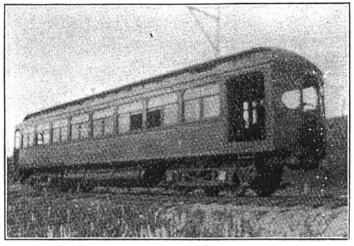
| Fig. 9. Arnold Single-Phase System. Complete Car. |
"Third A large reduction in the first cost of electrically equipping long-distance railroads, thereby making it feasible, from an engineering and business standpoint, to equip many roads which cannot now be shown advisable, thus opening up the steam-railway field to the industry in which we are now engaged."
The following description will explain more in detail the application of the principles of the system and the mechanism of its working parts:
Fig. 3 represents diagrammatically the working parts of one form of the system. The rotor (R) of a single-phase induction motor is geared to the axle of the car and by means of crank pin (C') secured in pinion (P) also drives the compressor cylinder (RC), while stator (S) can freely revolve around the rotor and drive, by means of crank pin (C) the compressor cylinder (SC). Both cylinders are piped to air reservoirs located under the car and are also provided with suitable valves manipulated from a single controller on the car platform for making them perform their various functions; thus the entire regulation of the speed and power of the car is controlled by the air cylinders, and no1 other regulating devices are necessary. The cylinder valves are electrically operated, which makes it possible for each cylinder when driven by the electric motor to compress air into the tanks and when operated by compressed air to furnish mechanical energy for moving the car. When, for instance, the cylinder is compressing air, the valves work like inlet and outlet poppet valves of a common air pump, while, on the other hand, if the cylinders are supplied with compressed air, each valve is operated electrically by a pilot solenoid connected with the valve seat in such a manner that the energy for moving the valve is supplied by the compressed air, thereby making the valve practically self-actuating. The time of operation of the valves is controlled by a series of collector rings, revolving with the engine shaft, and their regular operation is interrupted and varied to suit the requirements by means of the motorman's controller.
When a rotary or turbine type of air engine is used, all of the above valves and reciprocating parts are eliminated and the entire controlling mechanism themselves, and as these are below the car floor, the danger from the current is reduced to the minimum.
| |||
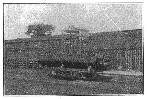
| Fig. 10. Arnold Single-Phase System. First Experimental Locomotive. |
At the same time the air cylinders, in addition to performing all the functions of speed control, give to the machine the independent-unit element, and the ability to store the kinetic energy of the train in stopping and utilize it in starting. On account of these and other features the electric motors of this system can be much smaller in capacity, when rated as continuous working motors, than those of other systems not possessing this equalizing-load feature, and the capacity of the power house and line can be reduced to about one-half of what would be required with systems where the fluctuating starting loads of the cars are transmitted back to the power house.
In order better to understand the different operations of the system, Fig. 4, showing a speed diagram, has been prepared, in which on the axis of abscissae (ODL) are represented the different car speeds in per cent. of the synchronous-motor speed, while the co-ordinate axis (AOB) represents the rotor and stator speeds corresponding to the car speeds shown.
The operation of the car may be divided into the following periods:
I. Standing in the Station. Referring to Fig. 3, the rotor (R) is standing still, while the stator (S) runs with full synchronous speed. The stator is then transferring the full energy of the electric motor through crank (C) to the compressor cylinder (SC), which energy is being delivered in form of compressed air into the air reservoir.
Since the relative velocity between the stator and the rotor is, under all conditions of operation, constant, the speed curves of stator and rotor may be represented by two parallel lines (OCR) and (ADS) in Fig. 4. The origin (O) of the given coordinate system represents the period of rest of the car, and, therefore, indicates zero rotor speed and full stator speed in a negative or downward direction, as the stator is now revolving in the opposite direction from that which the rotor must revolve to drive the car forward.
Let it be further assumed that for an instant (OA) equals the active torque of the stator, then it will be easily understood that (OB), which equals (OA), represents the reactive torque of the rotor exerted on the car axle, meaning that if the car is free to move, the reactive torque can be used advantageously for the starting and acceleration of the car.
When the car is standing in a station it is held at rest by moving the controller to such a position that the outlet pipe from rotor cylinder (RC) is throttled, thereby increasing the pressure behind the piston to such an extent that it overcomes the effort of the rotor (R) to revolve, thus tending to cause the stator (S) to revolve and at the same time holds the car at rest without the use of wheel brakes.
2. Starting and Accelerating. To start the car, the air cushion behind the piston of (RC), Fig. 3, is removed and the air which is being compressed by cylinder (SC), supplemented by the stored air from the tanks, is admitted to cylinder (RC), with the controller at the position of maximum cut-off. The rotor then begins to revolve, and as it accelerates the stator slows down by exactly the same amount that the rotor has increased its speed, and as the rotor and car speed increase the controller is gradually moved to a smaller percentage of cut-off until the car speed coresponds to the full synchronous speed of the motor, at which time the stator comes to rest.
During this period of acceleration the air compressed by cylinder (SC) instead of being delivered to the tanks to lose its heat, is delivered, hot, directly to the rotor cylinders, thus greatly increasing the efficiency of the combination, as the heat usually lost in air systems is utilized and the advantages of heated air gained without a reheater, and as the pressure used is low, many of the ordinary difficulties in the use of compressed air disappear. If the rate of acceleration is such that cylinder (RC) uses all of the air supplied by cylinder (SC), no exhaust to the atmosphere from cylinder (RC) takes place.
| |||
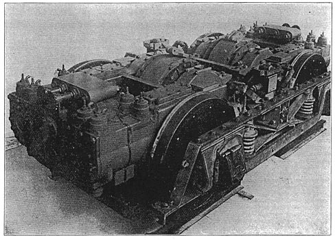
| Fig. 10. Arnold Single-Phase System. Latest Double-Motor Equipment. |
Referring now to Fig. 4, which graphically represents this process, since the electric motor runs always at a constant speed and a constant load, it has a constant torque, and, therefore, the distance between lines (OCR) and (ADS) may be considered as representing the energy delivered by the electric motor.
The length of any ordinate extending from (OD) to (OC) represents the proportionate amount of energy derived from the electric motor which is applied directly through pinion (P) and gear (G) of Fig. 3 to the propulsion of the car, while the corresponding ordinate extending below (OD) to (AD) represents the proportionate amount of the energy of the electric motor which is absorbed in compressing air through cylinder (SC), which energy, in the form of air, is immediately transferred to cylinder (RC) and is utilized in accelerating the car.
In practice, however, since there will be a loss in transferring the energy from electrical energy into energy in the form of compressed air and back again into mechanical energy, this loss, whatever it may be, must be drawn from the storage tanks, and the requisite amount of air from these tanks supplied to rotor cylinder (RC), in order to maintain the full power of the electric motor upon the car axle during the period of acceleration. Should it be desired to accelerate at a greater rate than full power of the electric motor is capable of giving to the car the additional energy may be supplied in the form of air from the storage tanks through cylinder (RC), thus increasing the total energy given to the car during acceleration, in which case this total power would be represented for any given instant by a point above line (BC).
3. Full Speed. When the rotor has reached full synchronous speed by the previous operation, this speed can be maintained by moving the controller to another position which will throttle the outlet pipe of cylinder (SC) until the reaction due to the pressure behind the piston equals the full capacity of the electric motor. An overload or underload may be placed upon the motor by varying this pressure, but under normal conditions of operation cylinder (SC) is provided with an automatic valve which keeps a constant pressure behind its piston, thus maintaining an absolutely constant load upon the electric motor and consequently a uniform demand of electrical energy from the line. This uniform load is represented by the parallel lines (OCR) and (ADS) of Fig. 4.
With the controller set at full-speed position the inlet valve of rotor cylinder (RC) are held open, and the piston runs free, and the electric motor now gives its full power to the car axle, and the stator and its air mechanism will remain at rest as long as the car runs at the speed corresponding to the synchronous speed of the motor.
4. Speed Variations. There are usually certain places on any road where high rates of speed can be maintained for short distances, and as these speeds might be higher than the synchronous speed for which the motor was designed, they are provided for as follows:
Assuming that the car is running at synchronous speed, the controller may be moved to such a position that the valves of stator cylinder (SC) operate in such a manner as to cause it to act as an engine and revolve stator (S) in the same direction as rotor (R) is revolving. This now causes, owing to the constantly electrically maintained relative difference in speed between the stator and the rotor, an increase of speed of the rotor and car axle, due to the motor automatically working as a magnetic clutch, without mechanical contact, and if the resistance of the car or train is less than the capacity of the electric motor, the air necessary for revolving the stator can be obtained, hot, from the rotor cylinder (RC) without drawing from the tanks and a speed above synchronism indirectly proportional to the resistance of the train maintained indefinitely. When the resistance of the train is greater than the capacity of the electric motor speeds above synchronism can be obtained only by supplying rotor cylinder (RC) with stored air from the tanks, and can only be maintained for short distances, or until the storage capacity of the air reservoirs is exhausted. This condition corresponds to the spurts that can be made by a steam locomotive when working above the steaming capacity of the boiler. The distance from the line (ODL) to that portion of the line (ADS) aoove (ODD in Fig. 4 represents, at any given speed, the proportionate amount of energy which must come from the tanks and be supplied through cylinder (SC), and the distance from (DL) to (CR) represents the total energy given to the car by the combined action of the electric motor and the stator cylinder when operating under these conditions.
The energy delivered to the car can be still farther increased by admitting air into rotor cylinder (RC) and allowing it to work as an engine.
5. Retardation. To bring the car or train to rest, instead of applying mechanical brakes to the wheels in the ordinary manner, and thereby dissipating the entire stored energy of the car or train in the form of heat, this energy is saved in the form of compressed air, to assist in starting the car or train by seting [sic] setting the controller in such a position that rotor cylinder (RC) compresses air and delivers it into the storage tanks. Any desired rate of retardation can be secured by throttling the delivery pipes from rotor cylinder (RC), and in practice this pipe is provided with an automatic valve which releases just before the slipping point of the wheels, thus allowing the motorman to brake as rapidly as he desires without liability of flattening the wheels. Supplemental wheel brakes are provided for emergency, but need not often be used, and the ordinary wear and tear on them is saved. When the car is again at rest the cycle of performance as above given is repeated for the next run.
6. Reversing. When it is desired to run the car backward for short distances, the electric motor is not disturbed and the power is furnished by the rotor cylinder (RC) by reversing the action of the valves, but if it is desired to run backward for any great distance the current is thrown off the motor, the stator engine reversed, and the stator brought to speed by the air, when the current is again thrown on to the motor, and the cycle of operation is the same as when running forward.
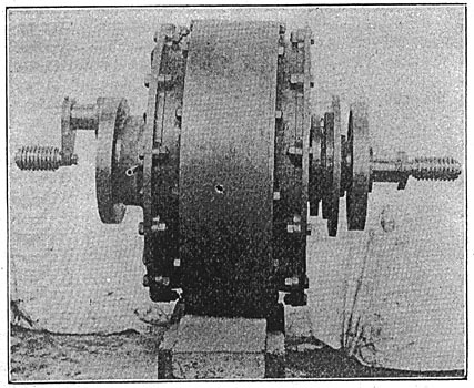
Fig. 5 represents the exterior of the electric motor, showing the cranks of the stator and rotor; also collector rings for operating the valves of the air cylinders when working as engines.
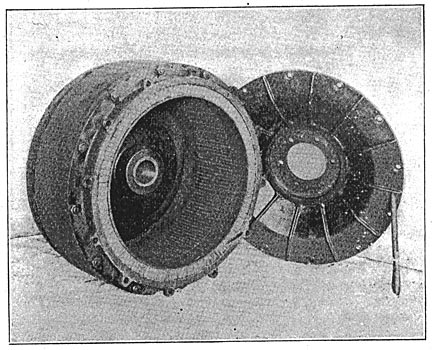
Fig. 6 shows an interior view of the stator of the motor with the flange removed, the rotor of the motor being of the standard squirrel-cage induction type.
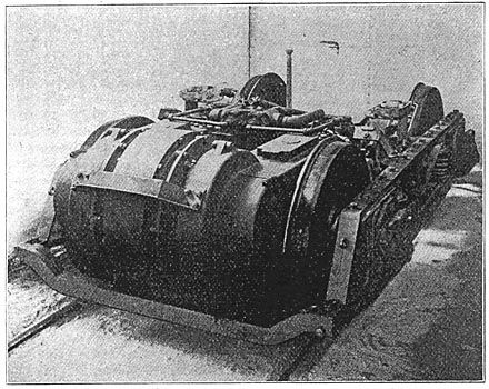
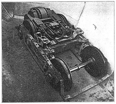
Figs. 7 and 8 show, mounted upon a truck, two views of the first electropneumatic motor constructed, and upon which the first experiments were conducted, while Fig. 9 shows one of the cars constructed for the system.
 |
| Fig. 12. Longitudinal Section. Arnold Single-Phase Electropneumatic Railway System. Drawings of Locomotive. |
Since the single motor represented in Figs. 7 and 8 was too small in capacity to propel so large a car, it was decided to experiment with an improvised locomotive, consisting of the truck and motor shown in Figs. 7 and 8, carrying suitable air tanks and transformers upon a temporary frame structure. This locomotive, shown in Fig. 10, was the one upon which the trial runs were made and passengers carried on June 15, 1902.
 |
| Fig. 13. Transverse Section. Arnold Single-Phase Electropneumatic Railway System. Drawings of Locomotive. |
Fig. 11 shows the end and side views of the new electropneumatic motor, constructed after the pre liminary experiments had been made on the first motor. For experimental purposes this truck was fitted up in the form of a locomotive, as shown in longitudinal and transverse section by Figs. 12 and 13, and it was this locomotive that was recently destroyed by fire. In order that the locomotive might operate as an independent air unit upon tracks not equipped with overhead electrical conductor, it was provided with a small storage battery and small motor-generator for charging the batteries and for operating the headlight. These auxiliaries are not necessary for the successful operation of the system, provided the locomotive can always be supplied with electric current from the working conductor, for then the valves can be made to operate from alternating current, and thus eliminate the use of motor- generator and batteries. When, however, it is desired to operate independently of the electric conductor these auxiliaries are necessary, and one set may supply an entire train. It will be seen that the locomotive is also provided with transformers, another auxiliary which is unnecessary in case the motors are designed for the voltage transmitted over the working conductor, but in this case transformers were used because the manufacturer of the motors could not be induced at the time they were purchased to build a high-tension motor for railway work, consequently the parts of a standard motor were utilized, and a pressure of 200 volts adopted for the motors, as this was the most economical voltage that could be used with the particular parts selected. This locomotive was provided with all necessary testing instruments and had been operated in the barns for some time and found to perform all its functions successfully, and would have been placed on the road and experiments with it would now be in process had it not been destroyed.
