[Trade Journal]
Publication: American Electrician
New York, NY, United States
vol. 13, no. 7, p. 321-324, col. 1-3,1-2
A WATER-POWER RAILWAY PLANT WITH
ALTERNATING-CURRENT TRANSMISSION.
TRANSMISSION PLANT AND SUB-STATIONS
OF THE KALAMAZOO VALLEY
ELECTRIC COMPANY.
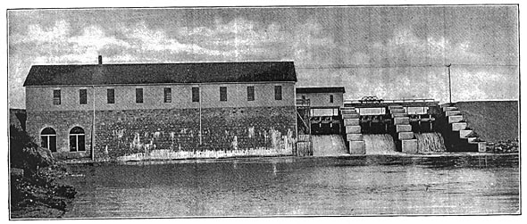
The Kalamazoo Valley Electric Company operates an extensive long-distance transmission system supplying electric light and power to sub-stations at Allegan, Otsego, Kalamazoo, Augusta, and Battle Creek, Mich. It takes its power from the Kalamazoo River, the generating plant being located at Trowbridge, five miles east of Allegan. From the power house one transmission line runs northwest to Allegan; the other runs southeast to Otsego and Kalamazoo and from there east to Augusta and Battle Creek. Kalamazoo is 22 miles and Battle Creek 46 miles from the power house. The transmission e.m.f. is 25,000 volts. The power plant is located at a dam on the Kalamazoo River which gives a head of 23 ft.; the dam is of wood with stone filling. A view of the dam, power house and flood gates is shown in Fig. 2. There are three 13 x12-ft. Taintor flood gates, which are raised by a crab located in the small extension at the right-hand end of the power house; this extension is directly above one of the flood gates, and the crab is arranged to be run out on tracks over the other two gates. The pond formed by the dam covers 600 acres and backs up the river about six miles.
| |||
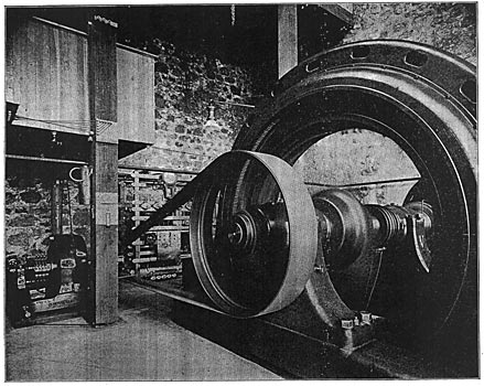
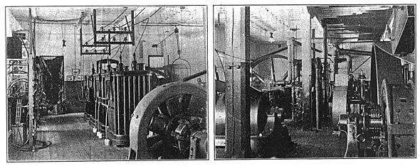
| Fig. 1. Direct-Driven Revolving-Field Alternator, Exciter and Switchboard. |
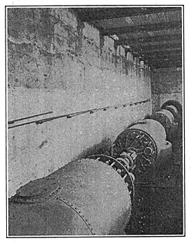
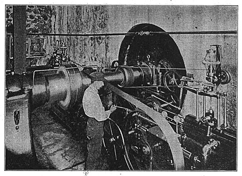
The wheel pit, the interior of which is shown in Fig. 3, contains four pairs of 45-in. horizontal Samson turbines all coupled to the same shaft and direct-connected to a 1500-k.w. generator. Each pair discharges into an 8-ft. draft-tube, and each draft-tube discharges into an elbow which has a horizontal outlet on the down-stream face of the structure. The turbines were built by James Leffel & co., of Springfield, Ohio, and have a combined rating of 2800 horse-power. Two pairs of the wheels are controlled by a Lombard governor and the other two by hand. The 10-in. shaft passes from the wheel pit through a stuffing box in the wall into the generator room. The Lombard governor, which is located in the generator room, is shown in Fig. 4.
| |||
| Fig. 2. Power Station and Dam at Allegan. |
The generator is a 1500-kw. three-phase General Electric machine with a revolving field magnet; it runs at 180 r.p.m. and delivers current at 2300 volts and 60 cycles. It is shown in Fig. 1, together with the exciter and the switchboard. It is not often that a power plant of this size puts "all its eggs in one basket" to the extent of depending on only one generator, and frequent interruptions from this cause were freely predicted when the plant was started, but its record has been very good. At times the generator runs for four months continuously without being shut down. In summer it cannot run as long as this because of the accumulation of very small bugs in the armature and field windings, which must be frequently cleaned out. When the machine is shut down it is done at a time when the old steam plants at the sub-stations can carry the load. The generator switchboard is extremely simple, containing only an oil break switch and automatic circuit-breaker and voltmeters and ammeters. The current is raised to 25,000 volts by a bank of three General Electric oil and water-cooled transformers of 500 kilowatts capacity each. The circulating water is supplied by a Worthington pump driven by a 1-h.p. direct-current motor which receives current from the exciter.
| |||
| Fig. 3. View in the Wheel Pit. |
There are two high-tension three-phase circuits to Kalamazoo and one to Allegan; the Kalamazoo lines are transposed through one complete spiral. From Kalamazoo to Battle Creek there is one circuit, with one complete spiral. The first line put in from the power house to Kalamazoo was galvanized iron wire, No. 4 Birmingham gauge. Later, when the load had increased, another line was put up of aluminum cable having a conductivity equal to No. 4 B. & S. copper. The shortest distance between two wires is 42 ins. The poles are 35 to 40 ft. in height and the line runs along the country road. All trees likely to interfere with the line were purchased and cut down. The cross-arms are 10 ft. long, of 3 3/4 x 4 3/4 ins. section. The pins are 15 ins. long and hold the insulators 7 ins. above the cross-arms. The insulators are the Provo No. 1 type made by the Hemingray Glass Company, of Covington, Ky. The telephone line is 7 ft. below the transmission line and is transposed at every fifth pole.
| |||
| Fig. 4. the Water-Wheel Regulators. |
It is important to note that although lightning has been so severe that it has splintered poles along the line, none of the transformers has suffered. At the power-house and sub-stations General Electric lightning arresters are used which interpose 34 gaps between the line and the ground. Very little trouble has been experienced from interruptions on the transmission line. A few boys have been prosecuted for breaking insulators. The sub-station at Allegan distributes current tor street arc lighting. It contains one 125-kw. step-down transformer which reduces the voltage from 25,000 to 2300, and two 25-light General Electric constant-current ("tub") transformers for supplying series alternating-current arc lamps. The Otsego sub-station furnishes both commercial and street arc lights and has the same equipment as the Allegan sub-station.
| |||
| Figs. 5. and 6 Two Views in the Sub-Station at Kalamazoo. |
The Kalamazoo sub-station apparatus is in the steam-equipped electric light station which formerly did the lighting of Kalamazoo. The steam plant is still kept in running condition as a partial reserve. A small addition was built on one end of the station building to accommodate the high-tension switches. The transforming apparatus at this sub-station consists of three 250-kw. step-down transformers for 2300-volt constant-potential distribution and three 250-kw. transformers for supplying 550-volt rotary converters. There are two 300-kw. rotaries; one supplies the company's 500-volt power circuit and the other delivers current to the electric railway lines of the Michigan Traction Company. The steam plant comprises two Lane & Bodley Corliss condensing engines with Dean jet condensers, belted to a line-shaft which is belted to a 250-kw. alternator; also a Lane & Bodley non-condensing Corliss engine arranged to drive four Thomson-Houston D-62 railway generators. The boiler plant contains one Heine water-tube boiler rated at 375 horse-power and five 80-h.p. horizontal tubular boilers, with Stilwell-Bierce & Smith-Vaile heaters. Figs. 5 and 6 are views in this station.
In the high-tension switch room the circuits are controlled by long-break knife switches, opened with a hook on the end of a long pole. The lighting circuits are all run out single phase from the sub-station. The voltage on these lines is regulated automatically, independently of the fluctuations in the supply, by an automatic regulator designed by Mr. James B. Foote, the electrical engineer of the company. These regulators are mounted on the single-phase switchboard, as shown in Fig. 7, and are very ingenious devices. The relays shown in the engraving have their armatures so balanced that any rise of voltage above the normal or drop of voltage below the normal makes a contact, closing the circuit through one of the solenoids of the electro-magnetic valve controller shown at the lower part of the switchboard just at the right of each regular dial. The valve operated by the solenoids controls the admission and release ports of a cylinder, the piston of which is geared to the shaft of the regulator; the cylinder is supplied with oil under pressure by a Lombard governor pump. The practical results obtained with this regulator are excellent, and the distribution voltage is held constant in spite of the fluctuations in the supply voltage due to the railway load. The regulator arm operates to cut in or out the coils of a boosting transformer; an ordinary "Type H" transformer was rewound for this purpose. These transformers are located just behind the regulator dials.
| |||
| Fig. 7. Switchboard in the Kalamazoo Sub-Station. |
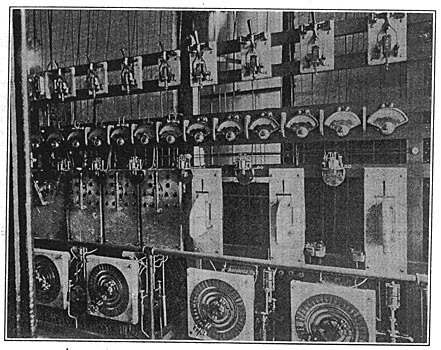
The lighting of the downtown district is supplied by three 100-kw. transformers hung on poles and feeding into a three-wire secondary distribution system. The rotary converters are equipped with a device to cause end play and distribute the brush wear. This device consists of a solenoid in the journal box which pulls the armature shaft over and is energized at intervals by means of a solenoid and plunger connected to a dash-pot and carrying a pair of carbon contacts. The journal of one of the rotaries with the wires leading to the solenoid is shown in Fig. 6.
The sub-station at Augusta has three 226-kw. water-cooled transformers supplied with cooling water by a pump gear-driven by a 1-h.p. General Electric motor. The transformers have two secondary windings, one for supplying a 550-volt 300-kw. rotary converter and one for the 2300-volt lighting distribution. The converter delivers current to the Michigan Traction Company's system. Both Galesburg and Augusta are lighted from this sub-station.
The Battle Creek sub-station is much like that at Kalamazoo except that both lighting circuits and rotaries are supplied from the same transformers, as at Augusta. The current here is metered to the local electric light company. All of the transforming apparatus and rotary converters operated by the company are of General Electric manufacture.
The officers of the Kalamazoo Valley Electric Company are Jackson men who are interested in other large projects in Michigan. Mr. James B. Foote is the treasurer and electrical engineer of the company and Mr. H. C. Hoagland is superintendent.
