[Trade Journal]
Publication: American Electrician
New York, NY, United States
vol. 13, no. 8, p. 385-388, col. 1-3,1
THE NEW BUFFALO TERMINAL TRANSFORMER
STATION OF THE CATARACT
POWER AND CONDUIT
COMPANY.
BY FRED P. WOODBURY.
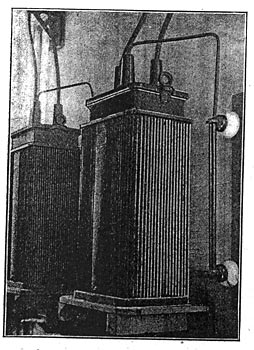
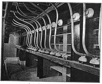
The new terminal transformer station of the Cataract Power and, Conduit Company, located at the corner of Niagara and Ontario streets, Buffalo, N. Y., represents the most advanced engineering practice. The building is an unimposing one-story brick structure, about 30 x 70 ft. A traveling crane of 12 tons capacity spans the entire interior. There are seven transformers in the station, connected in two batteries of three each with one to spare for an emergency. The primary and secondary switchboards are similar in design; each has two sets of bus-bars, three transformers being connected to each set. The transformers, each of 2250 kilowatts capacity, are of the standard Westinghouse oil-insulated, water-cooled type. A coil of iron pipe is secured to the inner surface of the tank through which the water circulates. The station receives about 14,000 kilowatts over three three-phase transmission lines from the power-house at Niagara Falls, at a e.m.f. of 22,000 volts, and delivers it at 11,000 volts three-phase to the underground system of the city. Fig. 1 is a view of the transformer plant, and Fig. 2 is a general view showing the transformers on one side, the primary 22,000-volt switchboard in the background, and the secondary or 11,000-volt switchboard at the right, with the circuit-breakers in the gallery above.
| |||
| Bob-Caption |
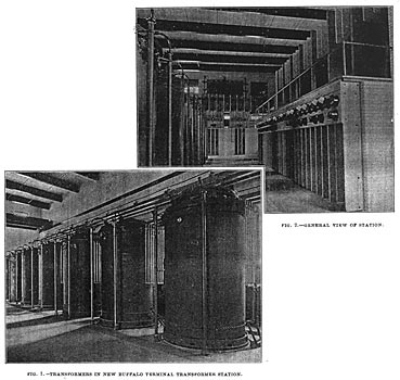
Fig. 4 is a diagram of the switchboard connections. The three transmission lines of three conductors each enter the building at the southerly end just below the eaves. The spark-gaps and ground wires of the Wurtz lightning arresters are connected just inside the wall, about 15 ft. above the floor. Then the conductors lead to the circuit-breakers, which are specially designed for the high voltage and are located at the top of the switchboard panels. Directly below each circuit-breaker is a "selector" switch by means of which the current may be delivered to either or both sets of transformers. Fig. 3 is a section of the feeder panels on the secondary switchboard and shows the construction of the selector switches.
| |||
| Fig. 3. Selector Switches. |
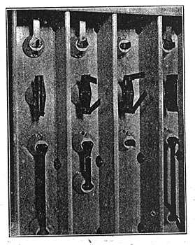
Fig. 5 is an outline sketch showing face and side views of these switches. Each switch has two arms which when not in use are closed firmly upon themselves like pocket-knife blades, as seen in the left of the picture; this is in order to avoid the accidental closing of the switches. When the switch is to be used one or both arms are swung through 180° and engage the contacts above and below. The switches are operated by means of a hook on the end of a long wooden pole which engages an eye in the end of the arm.
 |
| Bob-Caption |
From the high-tension bus-bars the current passes through "static interrupters" to the transformers. The static interrupter is a combination of choke coil-and condensor. The line is in series with the choke coil, and one end of the condensor is connected between the transformer to be protected and the choke coil. The other end of the condenser is connected to the ground through the fuse block shown at the right of the picture. Fig. 6 shows a static interrupter and Fig. 7 is a diagram of the connections. The condenser and choke coil are immersed in oil. The fuse block is similar to those used on the volt-meter transformers.
 |
| Fig. 5. Face and Side View of Switches. |
At the secondary switchboard the transformer terminals lead to the two central panels; the power may be switched to the bus-bars by selector switches, as on the primary board. On the back of the board at the switch, terminals are six condensers, one for each conductor, through which the ground detectors are connected, thus making it unnecessary to have metallic connection between the line and the ground detector. These detectors indicate the condition of the insulation of all the circuits in the station. From the secondary bus-bars the power passes to the feeders, seven in all. From the feeder switches the conductors pass through series transformers, for the instruments, to the circuit-breakers which are located in a gallery above the switch panels, and thence to the outside circuits, which are all underground except a temporary line to the Pan-American Exposition.
| |||
| Fig. 6. Static Interrupter. |
All the instruments are located on the secondary switchboard. The two transformer panels contain two ground detectors each, and these are the only instruments on these panels. On each feeder panel there are three indicating ammeters and two recording wattmeters. The ammeters and series coils of the wattmeters are connected to the secondaries of the series transformers, which have a ratio of 300:5 amperes. There are two potential transformers of a ratio of 12,000:100 volts for each set of bus-bars. These transformers are supported upon a wooden frame back of the switchboard, and they deliver to the voltmeters and the potential coils of the wattmeters.
 |
| Fig. 7. Diagram of Connections. |
On the end panel there is a voltmeter for each set of bus-bars, and there are, of course, the usual plugs and receptacles by means of which the instrument may be put across either leg of the circuit. The fusible cut-outs for the voltmeter transformers are very simple in construction. Each fuse is enclosed in a 1-in. fiber tube about 3 ft. long, with walls about 1/4 in. thick. A small hook is fitted in the side of the tube at each end, and a fine copper wire is drawn through the tube and secured by nuts on the shanks of the hooks. One end of the tube is closed with a heavy metal plug, and the tube is hung by the hooks in eyes at the end of the wire. The faces of the switch-boards are of gray marble, supported by brick columns. Marble barriers separate the switches and are placed between the circuit-breakers. Studs and bus-bars are thoroughly protected by slate barriers on the back of the board.
The circuit-breakers for the feeder circuits are arranged in sets, of three, each set being both tripped and restored together, so that in case of trouble all three conductors of the feeder will be opened simultaneously. Each set is fitted with a time-limit relay, comprising a clockwork mechanism which will not allow the circuit-breaker to open unless the overload continues for a predetermined time for which the relay is set. When the breaker is set to open at a certain current, should the line become loaded above this limit, the releasing trigger of the breaker is withdrawn and starts the time-limit relay, which locks the trigger before it has moved far enough to release the circuit-breaker. Should the overload continue to the expiration of the time for which the relay is set, the trigger is unlocked and the breaker opens; on the other hand, it the overload ceases before the time for which the relay is set has elapsed, the releasing trigger slips back into place and the relay resets itself.
| |||
| Fig. 8. Rear of Secondary Switchboard Showing Cable Connections. |
The circuit-breakers on the primary board are similar to those on the feeders, but in addition they are provided with reverse-current relays. This attachment is desirable where two or more transmission lines are run in parallel; if a short circuit occurs on one of the lines the parallel lines will tend to feed back through the sub-station and the circuit-breakers on the defective line will be promptly opened. The relay is built on the principle of a wattmeter. The potential coil is excited from an outside but constant source. The series coil is in series with the secondary of a series transformer whose primary is in the line. Should power be forced backward through the circuit-breaker from some other line, the reverse-current relay will connect a battery to the time-limit relay, and if the reversal of power continues beyond the period of time-limit, the circuit-breaker will be opened through the time-limit relay, as in the case of an ordinary overload.
Fig. 8 is a view behind the secondary switchboard, showing some of the cable connections. These are mounted on porcelain insulators, as are all of the conductors throughout the station.
The plant is entirely Westinghouse in design and construction, and under the management of Mr. L. E. Imlay, the company's engineer, who kindly supplied the illustrative material for this article. Mr. Imlay, assisted by Mr. James R. Newell, has brought the installation to completion within the last few months.
