[Trade Journal]
Publication: American Electrician
New York, NY, United States
vol. 14, no. 12, p. 578-580, col. 1-3
TELEPHONE ENGINEERING.
BY F. J. DOMMERQUE.
POLE FIXTURES.
Cross-arms are almost invariably made of wood, iron cross-arms being used only for supporting aerial cables. Long-leaf yellow pine is the best wood grown in this country from which to make cross-arms. The lumber should be free from all knots and imperfections, with a fine grain and sound heart. The cross-arms should be sawed from this and kiln-dried as thoroughly as possible, after which they should be given two coats of good waterproof paint. A reddish-brown metallic paint is generally used.
 |
| Fig. 1. Details of 10-Ft. Cross Arm. |
Cross-arms range in length from 30 ins. to 10 ft., and the latter measurement should be made the standard. As stated in a previous article, building a 10-ft. pole-line at the beginning prevents all future disputes as to right of way. For house connections, of course, small cross-arms are used advantageously; the present article is intended chiefly to relate to main pole-line construction. The standard lo-ft. cross-arm (Fig. 1) should be 4 1/4 ins. high and 3 3/4 ins. thick. The ends should be sawed off square and the two sides should be at right angles to the bottom plane, but the top should be chamfered or rounded to a radius of about 20 inches throughout the whole length of the arm, except 10 inches in the middle, where the arm is to be attached to the pole; there the top should be left perfectly level so as to fit fair and square into the "grain" of the pole. The chamfer serves to form a roof from which the rain and snow may slide off easily.
This cross-arm is bored with ten holes for the ten pins; the holes must be bored to fit the l 1/2-in. shank of the pin well; the holes to be along the center of the arm and spaced 12 ins. apart, center to center,. except at the middle where the arm sets into the grain; there 16 ins. should be left between the two holes nearest the pole. This leaves 4 ins. from the centers of the last holes to the ends.
The cross-arms are attached to the pole by two 1/2-in. lag screws or better by one 5/8-in. carriage bolt, the hole for this being drilled through the middle of the arm. If lag screws are used they should be 9 ins. long, and their thread should be cut so as to allow of their being driven part of the way home; they should be staggered so as not to weaken the arm too much. If carriage bolts are used, they should be long enough to reach through the pole and take a nut and one or two washers at the other end. Two more holes are to be drilled in the cross-arm for attaching the braces. These holes are to be on 30-in. centers, 15 ins. each way from the center of the pole, and large enough to allow a 1/2-in. carriage bolt to pass. All holes should be bored sharp and clean and so as to give a driving fit for the bolts, which will prevent moisture from entering.
In places where there is no fear of sleet loading the wires nor of high winds in short, where there is never a chance of unfavorable weather conditions a lighter 10-pine cross-arm may answer the purpose. Its length may be 8 1/2 ft., its height 3 3/4 ins., and its thickness 2 3/4 ins.; distance between pine hole centers 10 ins., except at the middle, where 16 ins. will be required, leaving 3 ins. from the center of the last pin to the end of the arm. The pins used with this arm are only 1 1/4 ins. diameter of shank; the lag screws are only 7 ins. long. For such cross-arms common pine is mostly used. At the end of a pole line, shorter and heavier cross-arms are used, with the pins set 9 ins. apart. Fig. 2 shows such cross-arms.
 |
| Fig. 2. Details of 8-Ft. Cross Arm. |
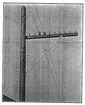
Alley-arms, as the name suggests, are used in alleys and are therefore encountered almost exclusively in cities. They are attached to the pole at one end, carrying all of the wires on one side of the pole. These should not carry less than ten pins, but they may be somewhat shorter than the standard cross-arm. The advantage of alley cross-arms lies in the ability to avoid crossing private property with the wires, thereby obviating any cause for complaint or damage suits, and also the use of high poles, as there are no houses or barns to be cleared. The alley-arm should always be of long-leafed yellow pine and drilled for 1 1/2-in. pin shanks.
As alley lines are almost invariably located in the rear of high buildings, barns or warehouses, there is not much danger from wind, and it is practical to locate the wires closer to each other than in the case of an ordinary exposed pole line. The holes for the pins, therefore, may be bored only 8 inches apart, center to center, leaving 4 inches from the center of the last hole to the free end of thf^arm and 26 inches from the center of the nearest hole to the end that, is secured to the pole, the arm being 8 1/2 feet long, 4 1/4 inches high and 3 1/4 inches thick. The alley-arm is chamfered or rounded on the top exactly like the cross-arm, excepting 10 inches of its length at the pole end. When used for carrying cables, alley-arms are frequently made 4 1/4 inches thick.
| |||
| Fig. 3. Alley Arms. |
The alley-arm is attached to the pole by a bolt or by two lag screws, and supported by two braces, the same as a standard cross-arm, but as the alley-arm sticks out a good way from the pole and is entirely unbalanced, an additional support is required at the far end. Many forms of support have been thought out for this purpose; the writer will describe only a few of them. This support is commonly called a "knee-brace," and is made of iron; either angle iron, round iron, flat iron or pipe. Fig. 3 shows an alley-arm supported by a knee-brace, which consists of angle iron 1 1/2 in. x 1 1/2 in. x 1/4 in., bent at the lower end and punched or drilled for two 1/2-in. lag screws, the holes being about 6 inches apart. The upper 6 inches of the angle are forged into a pipe so as to fit into the shoe. The shoe is of cast iron and galvanized; the knee-brace is also galvanized, and, in fact, all metal parts used on poles are now a-days galvanized bolts, screws, braces, etc. Two side extensions fit to the arm between the third and fourth outer pins; a carriage bolt holds the shoe to the arm passing through holes in the shoe-extensions and the arm. The shoe has an extension at the bottom, as shown in Fig. 4, into which the knee-brace fits loosely. This extension has a round hole into which the upper round end of the knee-brace is inserted before the lower end is spiked to the pole; this makes it unnecessary for a lineman to sit on the alley-arm before the knee-brace is attached.
 |
| Fig. 4. Shoe. |
After the knee-brace is inserted into the shoe, it may slip out again when a lineman would rest his foot on it; therefore the round hole in the shoe is provided with an annular recess, shown in Fig. 4 at A, and the knee-brace is provided with a pin, P, about 1/4 in. thick, which is introduced into the recess of the shoe through a slot S. This slot and the pin are set in such a relation that when the pin is slipped into the groove or recess the knee-brace must be given a quarter turn to bring it into the right position to be attached to the side of the pole; thus the pin and recess serve to lock the knee-brace to the arm.
As will be noticed in Fig. 4, the shoe is provided on each side with two ribs, R, which are there not only for strength, but also to serve as guides for extension braces or straps when more than one alley-arm is used on the pole. If there are two alley-arms, a strap 1 1/2 ins. x 3/8 in. of galvanized iron is set between the ribs on one side of the lower arm and held by the same carriage bolt that holds the shoe; the strap extends to the upper arm, to which it is bolted by another carriage bolt. With three alley-arms, the lowest arm receives one or two straps, one on each side, and the upper arm only one. Very often a single strap is used to tie all three arms together; in that case the strap is attached to one side only. Another form of knee-brace is illustrated in Fig. 5, which needs no further explanation.
Standard 10-pin long-leafed yellow pine cross-arms cost 3 1/2 cents per lineal foot, and last about eighteen years; 10-pin common pine cross-arms are worth the prices given below, and last about six years.
 |
Oregon pine has lately come in the market for cross-arms; it lasts up to twenty years. Knee-braces cost from 95 cents to $1.25, according to their greater or less complication; this includes the cost of the shoe also.
As all iron and steel parts used for pole fixtures should be galvanized, it may be opportune to insert here a method of testing. The piece to be tested is immersed four times in succession in a saturated solution of sulphate of copper, each immersion lasting about 70 seconds. If, after this, the piece appears black, the zinc has remained upon it, and it may be used; if copper deposits show, the zinc has come off and the piece should be rejected.
Braces. There should always be used two braces with each cross-arm; one would be sufficient to keep the cross-arm from turning on the bolt, but would not give the desired rigidity. It has in many cases been deemed advisable to use even four instead of two braces, mostly on poles where the arms are subjected to an extraordinary strain. In such cases the two extra braces are attached to the back of the cross-arm and pole. Fig. 6 shows the method of attaching the braces; A and B are the ordinarily used braces, and C and D are the back braces, if such are required. The braces are of galvanized steel, 24 ins. long, 1 in. wide, 1/4 in. thick and drilled at one end for a 1/2-in. lag-screw, and at the other end for a 1/2-in. carriage bolt, the holes being on 22-in. centers.
The carriage bolts that holds the braces to the arms are 4 1/2 inches long for yellow pine arms and 3 3/4 inches long for common pine arms. On each side of the arm a galvanized steel washer should be placed, one under the head and one under the nut of the bolt. These washers are round, 1 1/2 inches in diameter and 1/8 inch thick. A galvanized steel fetter drive screw will hold the two braces to the pole; this screw is 1/2 inch in diameter, from 4 to 5 inches long, and provided with a wood-thread for about three-quarters of its length, so that it may be driven home part of its way. Braces cost $70.00 a thousand, bought in lots of not less than 500. On larger lots there is from 5 to 15 per cent. discount. Carriage bolts, 4 1/2, ins. x 1/2 in., cost about $3.50 per 100; 3 3/4 in x 3/8 in. bolts, cost about $2 per 100. Fetter drive screws cost from $5 to $6 per 100.
| |||
| Fig. 5. Alley Arm. |
Pins. The only reliable insulator pin is made of locust, turned from the split wood. Oak pins cost half as much, and are not half as good. At corners of pole lines and places where an extra heavy strain comes on the pins, iron or steel pins have been used; but these are not much of an improvement, if any, upon locust pins, being liable to bend, and of high conductivity. The pin used with the standard 10-ft arm is 8 inches long, 4 inches being given to the shank (which in this case is 1 1/2 ins. average diameter), 1 7/8 ins. to the cone (which is 1 7/8 ins. in diameter at its lower end, forming the shoulder against cross-arm, and 1 1/4 ins. in diameter at its upper end, where the thread begins), and 2 1/8 ins. to the thread, which is cut so as to fit nicely into the insulator. (See Fig. 7.) There are about three threads to the inch and the thread is cut very nearly square, but not as sharp as it would be in the case of an iron screw-thread.
 |
| Fig. 6. Method of Bracing. |
The pins for the lighter 8 1/2 ft. crossarms have the same dimensions lengthwise, but the shank in this case is only 1 1/4 ins. average diameter and the shoulder 1 5/8 ins. (See Fig. 8.) The thread is the same in both cases. The shank is always a little tapered. The pins when delivered should be sound; the thread should be examined and pins with pieces broken out of the thread should be rejected. The pins are held in the cross-arms by wire nails driven through the side of the arm. Pins should be painted the same as the cross-arm and should be attached to the arms before putting on the pole. The price of 1 1/2-in. locust pins is $16 per 1,000; 1 1/4-in. oak pins cost $9 per 1,000; 1 1/4-in. locust pins cost $12 per 1,000, and 1 1/4-in. oak pins cost $6 per 1,000.
The pins just described are used on straight line work; on long-distance lines where the wires have to be transposed in certain intervals to avoid cross talk, a pin is used that allows of the attachment of a transposition insulator, which consists of two insulators, one on top of the other. The pins used for this purpose differ from the standard pins in the length of the cone, which is in that case 1 3/4 ins. long, and in the length of the screw thread, which is 3 1/4 ins. long. (See Figs. 9 and 10.)
Insulators. The material used for insulators in this country is glass, while European practice favors porcelain; both have their advantages. Porcelain is the better insulator, but it is more expensive than glass, and the glass insulator is commercially preferable in telephone work, the insulation being good enough and the price low. Glass insulators are moulded, and preferably of white or nearly white glass, so as to prevent insects from locating their homes inside the cavities; insects preferring dark spots for such purpose. Green glass is cheaper and probably somewhat stronger, but more opaque. The surface of the glass should be perfectly smooth so as to let the water run off easily and prevent soot and dust from collecting. The glass should of course be free from blow-holes, which impair its strength.
 |
| Figs. 7, 8, 9 and 10. |
The so-called "pony" insulators have found great favor in the telephone field; the pony insulator has a single groove for straight line work and a double groove for transposition lines. The standard or regular pattern of insulator is the heavier one and preferable. Of this type, the double one is used for transpositions. Fig 11 illustrates the single regular insulator, the grooves A, A' varying according to size of wire, and Fig. 12 the double one. The types of insulators are many; some have double petticoats, some have teats around the bottom edge; but the pony and the regular or standard are mostly used. Pony insulators range in price from $20 to $25 per 1,000, according to size and quantity. They are shipped in barrels, about 400 in a barrel. Sometimes transposition insulators are made of one piece; then the insulator is provided with two grooves and costs from $65 to $85 per 1,000. Two-piece transposition insulators cost from $103 to $133.50 per 1,000, according to size and quantity.
 |
| Fig. 11. Single Insulator. |
Pole Steps. There are two sizes of pole steps in use, both being made of galvanized steel. The lighter size is 9-16 in. in diameter and 9 in. long, the heavier one is 5/8 in. in diameter and 10 ins. long. Both have a wood thread cut at one end and are bent over about an inch at the other end so as to prevent the lineman's foot from slipping off. Pole steps are placed on both sides of the pole at right angles to the crossarms, and staggered; they are spaced on 30-in. centers on each side of the pole. The lowest step in about 10 feet above the surface of the ground. From there down wooden bracket steps are generally spiked to the pole on 36-in. centers, three on the front and two on the back of the pole. On poles of a very large diameter the steps are placed on only 24-in centers. A 30-ft. pole requires on the average eight pole steps; a 35-ft. pole, eleven; a 40-ft. pole, fourteen; a 45-ft. pole, eighteen; a 50-ft. pole, twenty-two. Pole steps in lots of 500 or less cost $50 per 1,000 for 5/8-in. diameter; $36 for 9-16-in., from which prices there is from 5 to 15 per cent. discount in larger lots.
 |
| Fig. 12. Double Insulator. |
Butt Guards. On street corners and in streets and alleys where the traffic is heavy, poles are provided with butt guards of sheet iron; these are 3-16 ins. thick and measure 18 ins. up and down and 24 ins. sidewise for large poles, and for small poles 15 ins. and 18 ins. respectively. Usually they come rolled to a diameter of about 14 or 15 inches and can be opened or closed to fit the pole. The holes in them are punched for 20-penny wire nails or spikes, the holes up and down being closer together than those horizontally; each plate requires about two pounds of spikes. Butt guards cost from 50 to 75 cents, according to size. Spikes are sold by the pound.
Protection-strips. Poles are frequently provided with, perpendicular protection strips, sometimes in addition to butt guards, sometimes without them. The length of the strips varies from 4 feet to 8 1/2 feet. The strips are of galvanized iron 2 inches wide and concaved so as to conform approximately to the rounding shape of the pole. A 30-ft. or 35-ft.pole requires eight protection strips; a 40-ft. pole, nine; a 45-ft. pole, ten; a 50-ft. pole, eleven. The protection strips are not punched for nails, but are attached to the pole by barbed nails driven in along the edge of the strip on about 9-in. centers vertically. From one to two pounds of nails are required, according to the length of the strips and the thickness of the pole. The protection strips cost from $4 to $6 per 100, according to length. Many telephone companies have attempted to wrap the poles for protection with either iron wire or iron straps, winding the wire in spirals around the pole and using staples in the case of wire and nails in the case of straps for holding. Such protection, however, is objectionable, as in case of a break in the wire or band the ends stick out from the pole and become dangerous to passers-by and also give the poles the appearance of neglect.
