[Trade Journal]
Publication: American Electrician
New York, NY, United States
vol. 16, no. 3, p. 142,143, col. 1-3,1
Application of Pupin's System to Telephone Circuits. — Recent experiments with the Pupin system prove that by the insertion of inductance coils in telephone circuits in the manner described by Prof. Pupin, the great advantages theoretically claimed are obtained in actual practice. Experiments were performed by F. Dolezalek and E. Ebeling on the Berlin-Potsdam cable and also on an overhead line between Berlin and Magdeburg, Germany. The cable between Berlin and Potsdam is about 32.5 km. (20.2 miles) long, and was laid by Siemens & Halske a few years ago for the German postal authorities to relieve the pole lines connecting the two places, and for intermediate local traffic. The cable contains 28 pairs of conductors of 1 mm. copper wire, with air space paper insulation, of the usual Siemens & Halske construction. This cable, with the exception of the portion in Berlin itself, is of U. G. type, lead-covered, armored and compounded; the portion in Berlin, being drawn into tubes, is without the compounded covering. Of these pairs 14 were left in their original condition, a most convenient arrangement, as it was thus possible by direct comparison between the equipped and unequipped lines to obtain a clear idea of the improvement gained. It was, of course, necessary in order to prevent disturbance of the cable, that the inductance coils should be introduced at the junction boxes already existing which connected the individual manufacturing lengths. The distance between the coils had, therefore, to be limited to certain definite figures. Inserting them at every second box, a distance of about 1,300 metres between the coils was secured. Each coil introduced a resistance of about 4.1 ohms in each wire of the circuit, and an inductance of about 0.062 henry. As the resistance of the cable conductor, with coils included, amounted to 23.5 ohms per kilometre, while the wire-to-wire capacity was about .037 mfd. per km., the value of the attenuation constant became 0.0106.
The self-induction of the simple metallic circuit measured with an alternating current of 900 periods per second, gave 0.0003 henry per km. The attenuation constant for the simple circuit was therefore 0.06 (at 900 periods). Consequently by insertion of the coils the inductance was increased 200-fold, and the attenuation constant reduced to one-sixth.
As a result of this large reduction in the attenuation a considerable improvement in audition was to be expected, and did, in fact, result. Comparing an equipped circuit with one of the simple circuits between Berlin and Potsdam, the length of which as mentioned was 32.5 km., an enormous difference was noticed in the loudness of the tones. While with an unequipped line the distance from the receiver for good audition could not exceed half a metre, with the equipped line audition was perfectly distinct at 10 metres distance, i. e., at the opposite end of the room. This experiment was conducted with the ordinary type of Siemens subscribers' instruments, the transmitter being actuated by two Hellesen cells. As there were at disposal 14 equipped and unequipped circuits, it was possible to experiment on longer circuits by joining single lengths in series.
Joining three lengths in series afforded a circuit of about 97.5 km., and comparing the equipped and simple circuits, the difference between the two was more striking than in the first case, when the speaking was carried on over a length of only 32.5 km. While it was possible with the equipped line to hear clearly at a good distance from the receiver, with the unloaded line the limit of audition had been reached, confirming with exactitude the results theoretically arrived at.
With five lengths joined in series, or a circuit of about 162.5 km. on the unloaded line, it was only a very accustomed ear that could recognize the slightest movement in the telephone diaphragm, while with the loaded line a very distinct, articulation was produced. By direct comparison of the loaded circuit of 162.5 km. with the unloaded circuit of 32.5 km. the loudness of tone was found to be approximately the same. Over 13 lengths in series, or about 422.5 km., reception was still possible, but the tones were very weak.
Comparing an overhead circuit between Berlin and Potsdam of 2 mm. bronze wire with a loaded circuit in the U. G. cable of the same length, the loudness of speech was approximately the same. The results depended a little on the state of the atmosphere. In good weather the loudness on the overhead wire was a very little greater than on the cable, while in bad weather the converse obtained, the cable circuit being a little louder than the overhead.
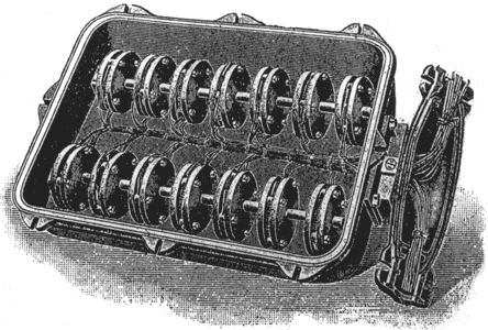
The result of this comparison is most noteworthy, inasmuch as it shows that by application of Pupin's system, a cable with a conductor of 1 mm. diameter can be rendered equivalent in speaking capacity to an ordinary unequipped overhead wire of 2 mm. diameter, or four times the section. Theoretical calculations show that this result was to be expected, but still it presents a striking confirmation of the correctness of Prof. Pupin's views. The arrangement of the inductance coils was very simple. Each set of 14 coils of annular construction was inserted in an iron box, and the necessary connections to the cable made by means of a special connection box, both being subsequently filled up with compound. Fig. 1, taken from the Electrotechnischer Anzeiger, gives a view of such a box with the connections complete.
 |
| Fig. 1. — Arrangement of Inductance Coils. |
After this satisfactory conclusion of the cable experiment, the German postal authorities placed at the disposal of Siemens & Halske for equipment a bronze overhead line of 2 mm. diameter, about 150 km. long, connecting the cities of Berlin and Magdeburg, and serving for the inter-communication of six intermediate stations connected along the line; this could be compared with a line of 3-mm. bronze wire about 180 km. in length, serving for direct communication alone between the same places.
 |
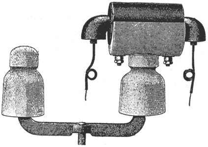
| Fig. 2. — Double Insulator. |
Before the loading of the 2-mm. circuit, the communication over the whole length was naturally inferior to that on the 3-mm. circuit. The 2-mm. line was now equipped with Pupin coils, a condition being imposed that no interference with traffic should be caused, the compliance with which presented no difficulty. At every 4 km. distance was inserted a coil of about 6 ohms resistance and 0.08 henry inductance. On the completion of the loading, the speech over this line was considerably louder than over the 3-mm. line. The installation of the coils was so arranged that at the poles where they were to be inserted double insulators were affixed, on one of which the coil had been mounted, as shown in Fig. 2, and in this manner the alteration was effected without affecting the insulation of the line. In the course of this experiment it was discovered that each such coil must be provided with a lightning protector; this could have been so arranged that at both ends of the coil the discharge would be led to earth, but as actually erected the coils were bridged by a vacuum protector.
