[Trade Journal]
Publication: American Electrician
New York, NY, United States
vol. 15, no. 8, p. 387-393, col. 1-3.1
MODERN RAILWAY POWER STATION AND SUB-STATIONS.
NEW HIGH TENSION ALTERNATING-CURRENT
INSTALLATION OF THE BERKSHIRE
STREET RAILWAY COMPANY
AT PITTSFIELD, MASS.
BY W. G. VIALL.
One of the finest interurban properties in New England is that of the Berkshire Street Railway Company. Starting in the town of Cheshire, Mass., where connection is made with the Hoosac Valley Street Railway of North Adams, the Berkshire Street Railway runs through the towns of Cheshire and Berkshire to Pittsfield, whence the line strikes south, touching the towns of Lenox, Lee, Stockbridge, Great Barrington and Sheffield, to the Connecticut state tine, forming practically a continuous electric railway from the state line of Vermont to that of Connecticut, and traversing the extreme western end of Massachusetts. In the not too distant future it is the expectation of the Berkshire company to extend its lines so as to connect with the lines of the Albany & Hudson Railway & Power Company, running between Albany and Hudson, N. Y. Connection will also be made with the Western Massachusetts Street Railway Company's lines, now being built between Westfield and Lee. These lines will also connect with the lines running to Springfield.
| |||
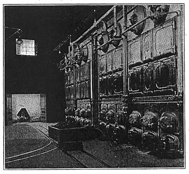
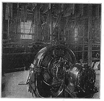
| Fig. 1. General View of Engine Room in Main Power Station of Berkshire Street Railway Company. |
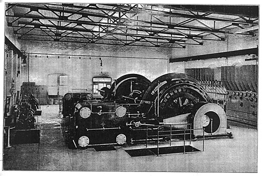
In arranging the power scheme, consideration was given to the general territorial lay-out, as well as to the present and future demands of the service. Decision was finally made in favor of a central generating station at Pittsfield, Mass., with a substation at Lee and another at Housatonic, the former of which is about 10 miles distant from Pittsfield and the latter 20 miles. Three-phase current at 13,300 volts is generated at the central generating station and transmitted directly to the transmission lines without the use of step-up transformers. This current is stepped down to 380 volts for use at the rotaries, of which there are two 300-kw. machines in the main station and two 250-kw. machines in each of the two sub-stations. The rotaries deliver direct current at 600 volts to the trolley wire. The general dimensions of the power house are 108 feet wide by no feet long, the engine room being 107 by 61 feet and the boiler room 42 by 95 feet, a brick wall separating the two. The engine-room floor is 8 feet 8 inches above the level of the boiler-room floor, and below the engine room is a basement the floor of which is 12 feet below that of the engine room. This forms a condenser pit wherein are located the condensers and steam and water piping, also the primary heaters, thereby leaving the engine room unobstructed in this respect.
 |
| Fig. 2. Cross-Sectional Elevation of Power Station. |
Steam is generated in four 380-h.p. water-tube boilers set in two batteries, built by the Aultman & Taylor Machinery Company, of Mansfield, Ohio. Each boiler has 3,930 square feet of heating surface arranged in 4-inch tubes in sixteen sections, each section being twelve tubes high. The grate surface of each furnace is 69 square feet, and steam is carried at 150 pounds pressure. The boilers are hand fired, bituminous coal being brought to the rear wall of the power house on an elevated spur from the main line of the Boston & Albany Railroad and dumped in front of the door leading to the boiler room. It is carried to the furnace doors, as shown by Fig. 7, on specially constructed side-dumping hand cars running on narrow-gauge tracks. Cars are also provided for removing the ashes. This coal-handling tramway was installed by The Hosher-Platt Company, of New York City. A Custodis stack, 75 feet 8 inches high and 8 feet in diameter at the top, adjoins the power house.
 |
| Fig. 3. Plan View and Elevation of Main Exhaust Piping. |
For supplying water, each condenser has a 10-inch independent cast-iron suction pipe leading from a cold well 10 feet deep sunk in the bed of the Housatonic River. There is a 6-inch suction pipe leading to the boiler feed-pumps in the boiler room. The hot well is outside the building, the discharge pipes to the well from the condensers being 16 inches in diameter or 2 1/2 times the area of the injection pipe. The connection from the well to the feed-pump is 6 inches in diameter. The intake pipes also have connection with the city water mains, so that there is no question of the available supply of water. A 6 x 6 x 6-inch Warren duplex pump, made by the Warren (Mass.) Steam Pump Company, discharges water through a 4-inch wrought-iron line to the primary heaters, and from them in a brass pipe to a 2000-h.p, Cochran auxiliary feed-water heater, furnished by the Harrison Safety Boiler Works, of Philadelphia. The feed-water pumps are of Warren make with cylinders 10 x 6 x 12 inches. The design is such that the small or low-pressure pump can also discharge directly into the Cochran heater and the boiler feed-pumps can also receive the water from the hot and cold wells and pump either directly into the boilers or through the primary heaters and thence into the boilers. The open heater receives the steam from the exciter units and the steam pumps, also the condensation of the heating system for the building, and the drips from the engine receivers, each of the receivers being provided with a trap for that purpose. The auxiliary exhaust is cross-connected to the main exhaust in the boiler room by a valve in the cross-section, so that when desired the main exhaust riser can be used to carry off the exhaust from the auxiliary plant, or the exhaust from the main engines may be utilized in part in the auxiliary or secondary heater. The boiler feed-pumps can be controlled by means of an automatic valve inserted in the live steam supply to them, this valve being actuated by the/level of water in the heater.
 |
| Fig. 4. Plan View of Main Steam Piping. |
All the steam piping is extra strong with Chapman valves and Crane fittings. The steam piping system includes two steam headers, one 14 inches in diameter for the main engine and the other for the auxiliary apparatus. An 8-inch connection starting from an automatic stop-and-check valve and bending horizontally and then vertically downward to the heater, where there is a gate valve controlling the boiler supply pipe, leads from the cross-connection between the two 42-inch drums on each boiler. The header is about 6 feet above the floor. Steam is conveyed to each engine through an 8-inch connection leading horizontally from the header to a point beneath the engine-room floor directly under the engine cylinder. The connection there turns upward through the floor to the cylinder, first passing through a Cochran separator. The piping is so arranged that live steam can be fed to each of the cylinders should occasion require it. In the branch leading to the low-pressure cylinder is a Kieley valve, by means of which the mean effective pressure in the low-pressure cylinder can be regulated throughout a considerable range. Condensation is taken care of by an adaptation of the Holly system, installed by Westinghouse, Church, Kerr & Co.
 |
| Fig. 5. End and Side Elevations of Main Steam Piping. Fig. 6. |
In the lay-out, as designed for the exhaust piping, the high-pressure cylinder exhausts into a receiver, or when the low-pressure cylinder is out of commission, into the main exhaust header. This header is 16 inches in diameter and towards each end feeds through a primary feed-water heater. This heater is arranged with valves, so that if necessary the exhaust into one end can pass through the exhaust outlets corresponding to the other unit. The feed-water heaters are 1000-h.p. units of the Goubert horizontal type. Just beyond the heaters are vertical twin jet condensers built by the Warren Steam Pump Company. At this point is the relief valve for service when running non-condensing. The auxiliary feed-water heater, together with the feed and circulating pumps, are located in the boiler room. The auxiliary header is just below the main header, near the wall separating the boiler and engine rooms. The connection from each boiler is fitted with an automatic valve at the boiler, and the battery is controlled by a gate valve immediately above the header. The connections to the exciter units, steam pumps and other auxiliaries are taken from the top. Figs. 4, 5 and 6 show the plan view and end and side elevations of the main steam piping, and Fig. 3 gives a plan and elevation of the main exhaust piping.
| |||
| Fig. 7. Boiler Room. |
The main generating units are each driven by a 1,200 h.p horizontal cross-compound condensing direct-connected Race & Sargent engine, built by the Providence Engineering Works, Providence, R. I. The general dimensions of the engines are as follows:
 |
Under a steam pressure of 150 pounds and at one-quarter cut-off, the rating is 1120 horse-power; at six-tenths cut-off the rating is 2150 horse-power. As is usual in the Rice & Sargent design, the cylinders are made of close-grained cast-iron with faced heads and pistons and water relief valves at each end. The exhaust valves are shaped according to this company's patented design, the steam passage's being formed in the valves themselves instead of in the cylinders. The valve gear is. of the Rice & Sargent patented rotary 4-valve type with independent eccentrics for the steam and exhaust valves. The point of cut-off is controlled by the governor from zero to three-quarter stroke. The governor is of the improved inertia type, guaranteed to regulate within one per cent from no load to full load and within two per cent for any instantaneous variation under any condition of load. A Monarch engine stop is provided to immediately stop admission of steam to the cylinder should the governor become disabled. The governor has control of both cylinders, and the low-pressure gear may be manually controlled while the engine is in operation, so that the relation. of cut-off from one cylinder to the other may be changed to suit the load. The receiver is of the overhead type with a capacity four times that of the high-pressure cylinder. The coils are sufficient to superheat the incoming steam so that there is no appreciable drop to the low-pressure cylinder. A 3-in. pop safety valve is provided on the receiver and set at 40 pounds.
| |||
| Fig. 8. View of Main Switchboard. |
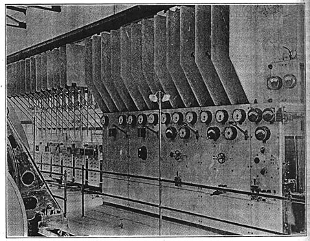
The main generating units comprise two 750-kw. three-phase revolving field Westinghouse alternators, giving 32.6 amperes per phase at 13,300 volts and 25 cycles per second. The stationary armature is thoroughly protected and the design of the machine is such that it is impossible to come in contact with any of the high-potential parts. Each alternator is excited by its own exciter set consisting of a 20-kw. Westinghouse 125-volt generator driven by a small Westinghouse steam engine. These exciter units are shown at the left in Fig. 1, and at night, when the main engines are shut down, these units supply current for lighting the station and car house.
| |||
| Fig. 9. Rear of Main Switchboard. |
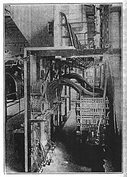
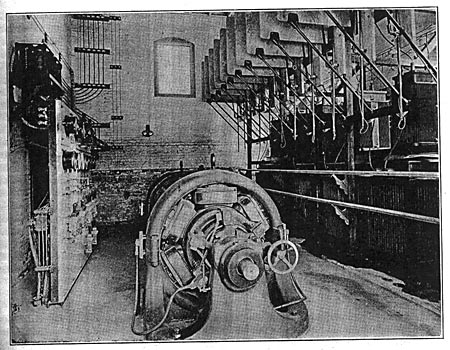
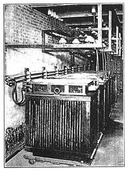
A view of the switchboard, which was installed by the Westinghouse Electric & Manufacturing Company, is shown by Fig. 8 herewith, and a diagram of the connections is given by Fig. 14. The board is of blue Vermont marble, 2 inches thick, polished on face and bevel. All of the metal parts on the face of the board are given a copper finish. The construction of the switchboard and its connections are shown so clearly in the illustrations and also in Fig. 9, which is a view taken from the rear, that further comment is unnecessary. Two 300-kw. rotary converters with their switchboard and six 100-kw. oil-cooled transformers complete the equipment of the main station. These converters are used to furnish direct current to the territory immediately adjoining the station and to the northern end of the line. Fig. 10 shows these machines and the switchboard. The connections are shown in Fig. 14. A system of compressed air is used for cleaning the electric machinery and furnishing air for the oiling system.
| |||
| Fig. 10. Motor-Generators in Main Station. |
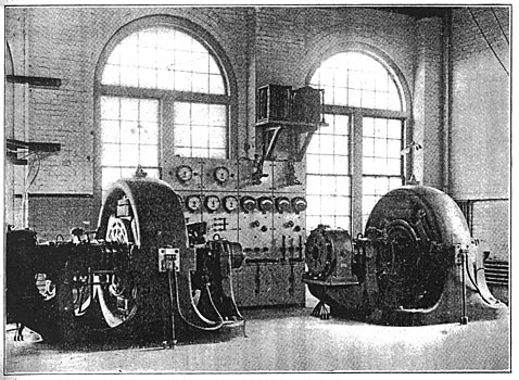
Fig. 13 is a view in the sub-station at Lee, showing the 250-kw. rotary converters and the static transformers. The plant is housed in a frame building, a portion of which is used as a dwelling for the sub- station attendant, the converters and transformers being in a one-story addition adjoining the rear of the building. The sub-station at Housatonic is located in the rear of the car house, and the electrical equipment is identical with that of the sub-station at Lee. A view of the equipment at this sub-station is given by Fig. 11.
| |||
| Fig. 11. Equipment in Housatonic Sub-Station. |
The transmission lines from the main station in Pittsfield are in duplicate; that is, there is one circuit from Pittsfield to the Lee sub-station and another circuit from Pittsfield to the Housatonic sub-station. These, are so arranged that in case of accident to either circuit, the other can be cut in. The transmission line does not follow the street railway line for the entire distance, the town of Pittsfield being cut out by a high-tension line around the city, and the town of Lee being similarly avoided by a line running over the turnpike. This not only avoids high-tension lines in the towns, but also shortens the transmission distance considerably. The transmission lines are of bare copper wire carried on two crossarms, the circuit to Lee being on one side of the pole and the circuit to Housatonic being on the other. Each circuit is arranged, as shown in Fig. 15, in the form of an equilateral triangle with sides 18 inches long. The pole-top shown herewith is the form used both where the transmission pole line follows the track and also where it goes across country. The insulators for the high-tension line are of glass having 7 1/2-in. petticoats and supported on steel pins with glass sleeves. A four-point barb wire strung along the tops of the poles and grounded at every fifth pole affords lightning protection. No poles are guyed on the transmission line, the sharp turns at the poles being braced by stubs set on the inside of the curve. The feeders for the trolley are carried on a cross-arm below the transmission arms and are tapped to the trolley wire every mile. Along the main line two No. 0000 hard-drawn copper-grooved trolley wires are used, supported by Craigehead flexible brackets on 35-ft. poles. The road is single track for a considerable distance, and the trolley wires are placed about 3 inches apart, except at the turnouts where they separate to accommodate both tracks.
| |||
| Fig. 12. Transformers in Main Station. |
Telephones are installed at all important points along the line. Each car is equipped with a portable telephone and a 15-ft. bamboo pole with two spring brass hooks at the top, and a long flexible twin wire with a jack plug at the other end for connecting to the telephone. The telephone wires are run along the pole lines about 18 feet above the ground, one above the other and separated about 15 inches, so that in case of accident communication may be had between the car and the main office from any point on the line. At every turnout, conductors signal the train dispatcher at the main station and report. An electric signal system, built by the United States Signal Company, of West Newton, Mass., and especially designed for single-track trolley roads, is used to show whether the section to the next turnout is free or not. The system consists of two signal boxes and two trolley boxes for every section of track between turnouts. The signal boxes, which are placed a short distance beyond the turnouts, are provided with windows of red and white glass, an incandescent lamp being placed behind each window. The boxes are connected by two No. 12 galvanized-iron wires. The armature of the lighting magnet is mechanically locked in place after it has operated the proper contacts and should the lamps be extinguished, owing to failure of current, they will be immediately relighted when the current is switched on again and can only be permanently
| |||
| Fig. 13. Equipment in Lee Sub-Station. |
extinguished by the action of the extinguishing magnet. This magnet unlocks the armature of the lighting magnet when the car leaves the block, thus replacing the signal in a position ready to work in either direction. When a signal is set either way, the signal for the opposite direction is mechanically locked out of service. The operation of this system is substantially as follows: When a car enters a block it actuates the mechanism in the trolley box, causing current to pass for an instant through a magnet whose armature being thus attracted is locked in place; this closes the lighting circuit through a permanent connection to the trolley or feed wire and lights a white light at the end of the block near the car and a red light at the other end of the block. The two lamps being in series, both are lighted simultaneously, and a motorman entering the block and seeing the white signal knows that the red signal is set at the other end.
 |
| Fig. 14. Diagram of Switchboard Connections. |
The track construction is first-class in every respect, 70-lb. T-rails in 20-ft. lengths are laid on 6 x 7-in. x 8-ft. ties spaced on 2-ft. centers, the maximum grade being 5 per cent. All joints are bonded with double No. 0000 flexible protected bonds. The line runs through the public highway, except in a few places where private right of-way was obtained. Three car barns are in use, one at Pittsfield, one at Lee, and one at Housatonic. The largest of the three is at Pittsfield and is located west of the main generating station. It is designed to accommodate 24 cars on 6 tracks, each track having a pit for making repairs on trucks and equipments. In an addition, built on the side next to the street, are the main offices and employes' rooms, and in the addition on the other side of the building are the wagon rooms, stable, and sand and oil rooms. A repair shop is to be built at the rear end of the car barn, which will be, equipped with modern appliances, for making repairs
 |
| Fig. 15. Transmission Line. |
and for painting. The car barn at Lee is a wooden building designed to accommodate 6 cars on 3 tracks, and the barn at Housatonic is designed to accommodate 3 cars on 2 tracks, one track being shortened to provide a waiting room for passengers. The rear end of this barn is used for the sub-station. The tracks in both the Lee and Housatonic barns have pits for making minor repairs. The rolling stock consists of 47-ft. convertible cars, each of which is equipped with four Westinghouse No. 56 motors with Type K-14 controllers; Christensen air-brakes, with independent electric air compressors, are provided for each car. The line now in operation is divided up as follows:
|
