[Trade Journal]
Publication: American Electrician
New York, NY, United States
vol. 15, no. 8, p. 394-396, col. 3,1-3
TELEPHONE ENGINEERING.
Stringing Outdoor Wires.
BY F. J. DOMMERQUE.
Insulators are not put on the pins until everything is in readiness for stringing the wires. If only one or two, or a few, wires are strung at a time a single reel may do, mounted upon a hand barrow and carried along the line by two men paying out the wire as they go; or the reel may be mounted upon a cart drawn by a horse. Fig. 1 illustrates a reel with adjustable pins which is used to a great extent in Germany and differs from the ordinary reel in being fitted with slots in which the pins slide. The upper cross with the slots turns around a pivot and is provided with rollers which travel upon a ring, to reduce friction. Fig. 2 shows a similar reel of iron manufactured in this country.
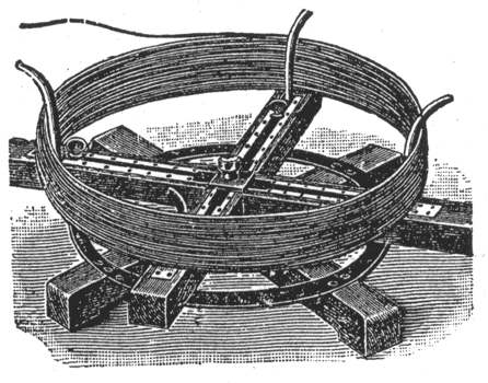 |
| Fig. 1. — Adjustable Reel. |
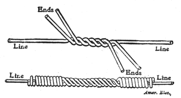
In unrolling the wire from the reel as the latter is carried along the line, care must be taken that it does not become kinked or twisted around its own axis, as thereby its strength is greatly impaired. When the wire is in place any irregularity in unrolling it may be traced by the wavy appearance that it will have. When one coil of wire is used up, another coil has to be joined to it, of course. Copper wire joints or splices are made with either McIntire or American sleeves, which have been mentioned previously. The ends of the wires to be jointed are pushed through the sleeve, as shown in Fig. 3, and then the sleeve is given five twists, giving the joint the appearance shown in Fig. 4. For twisting, two pairs of splicing clamps with holes fitting the sleeve are used. Iron wire joints are made with iron wire sleeves or with the so-called "Western Union" joint. In this case the wires are first twisted and then the end of one wire wound around the other, as illustrated in Fig. 5.
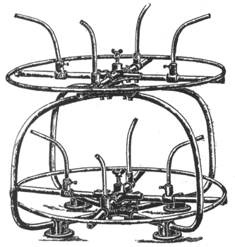 |
| Fig. 2. — Adjustable Reel. |
There is still another splice in use: the so-called "three-wire splice" where a piece of wire from 8 to 12 inches long is placed alongside the two ends of the line wires to be joined, and all three are then clamped in the middle by the tool and twisted like an ordinary wire joint, except that there are two ends to wrap around at each end instead of one. This joint is shown in Fig. 6; it is much stronger than the ordinary joint and naturally of better conductivity.
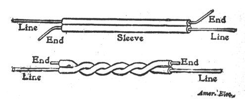 |
| Fig. 3. and 4. — Sleeve Connection. |
These hand-made joints need soldering; as a flux, resin should be used so as to avoid corrosion in the future. The solder consists best of three parts lead and two parts tin, melted and kept molten in a pot over a soldering furnace; into this pot the joint dipped. After the joint is soldered, it must cool off slowly and should not be dropped too soon upon damp ground.
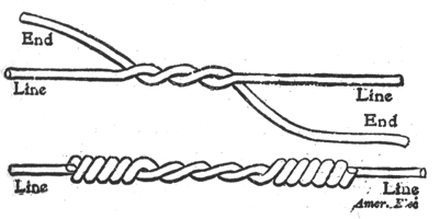 |
| Fig. 5. — Ordinary Splice. |
If a large number of wires must be strung at the same time, the cart may be provided with a frame carrying several reels side by side, usually ten, corresponding in number and position to the ten pins on the cross-arm, the reels being mounted so that they can be removed and refilled. Each reel ought to be provided with a brake so that the speed of the reels may be regulated individually; otherwise the wires may become tangled in paying out. The so-called "running board" is also used for stringing a greater number of wires. A number of coils, ten if all the pins on the cross-arm are to be used, are put on reels at the first pole and each one of the wires is threaded through a hole in a board (the running board), the holes having the same spacing as the pins. To the center of the running board a rope is fastened and by means of this rope the board is lifted over the first pole so that the wires rest on the cross-arm; then a team of horses is hitched to the rope, "walking away" with it and thus pulling the wires over the cross-arms. A man stationed on each cross-arm guides the wires over the arm, which is by no means easy.
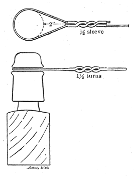
As soon as the wires are stretched across the arms the men on the poles begin tying them. As a rule the line commences at a cable pole, or if the line is the continuation of another line, at a corner pole, and terminates at an anchor pole; therefore, two ends of the line are "dead-ended." The method of dead-ending is shown in Fig. 7. The end of the wire is pushed through one side of a half-sleeve joint and its free end is then bent around the insulator and pushed through the other side of the half-sleeve; then the sleeve joint is given one and one-half turns, leaving the eye opening two inches. On straight lines the wires are placed on the sides of the insulators toward the pole, except, the two wires adjacent to the pole, these being placed on the outer, sides of the insulators. On curves and at corners, all wires are placed on the sides of the insulators toward, the outside of. the curve or corner — the "off" sides.
 |
| Fig. 6. — Three-Wire Splice. |
Before the line wire can be tied it must be given the proper "sag." As is well known, the wire forms between two poles a more or less flat curve, the form of which is mathematically termed a catenary, but can be considered a parabola on account of its flatness. The curvature depends on the tension in the wire. The tension in the deepest point of the curve depends on the weight, on the elasticity of the wire, the temperature, and the distance between the two adjacent poles. With increasing temperature the wire expands, which increases the sag and decreases the tension; contrary-wise, a decrease in temperature contracts the wire and decreases the sag, while increasing the tension. The wire elongates with increasing tension and contracts with decreasing tension. The amount of tension put on a wire should not be more than one-half its ultimate strength at the highest temperature and need not be more than one-sixth of its ultimate strength at the lowest temperature.
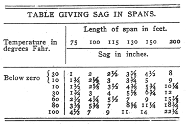 |
A table has been calculated giving the tension for the different temperatures at which wires are strung, taking into account the distance between poles and the size of wire, but to regulate the sag of wires by such tables a reliable dynamometer is required. The dynamometer is a strong spring balance and is attached with one end to the insulator. This method is too complicated for the ordinary lineman, though it is technically the correct method. The accompanying table gives the sag in inches required for a certain span at a certain temperature, without necessitating the use of a dynamometer, this table holds good for copper as well as iron wire. The table has been calculated for an ultimate strength of copper or iron of 60,000 pounds to the square inch and an assumed factor of safety of about 3 at a temperature of 10° Fahr.; the table has been used by telegraph and telephone companies to a great extent and is, therefore, sanctioned by practice.
 |
| Fig. 7. — Method of Dead Ending. |
In order to obtain the right sag between poles the men on the poles "sight the wires." The sighting begins at the first pole, of course. There are various methods of measuring off the sag; some linemen sight by the known distances of objects on the pole, as for instance, by the bottom of the glass insulators as being equivalent to two inches, the top of the cross-arms being equivalent to 3 1/2 inches, the bottom of the cross-arms being equivalent to 8 inches, etc. A better method is to provide a rod having at its top end a scale of inches and a slide with a projecting pin arranged to slip up and down this scale. Set the pin at each span for the required sag and have a man set the rod up at the center of the span and adjust its height until the lineman sights the top of the rod in line with the grooves on the insulators; then the wire is pulled up until it touches the pin on the scale. For pulling the wire up the "come-along" is used. In case several wires are put up on the same cross-arm, the sighting can be done from the ground after the first wire is tied. The man goes far enough away from the line so that he can see when the other wires come up to the level of the first one and then gives the signal to tie in. Where the line is running down hill, the man with the rod has to follow the deepest point of the curve in the wire and the wire must be tied in quickly so as to prevent it from slipping through toward the lower pole.
Transpositions.
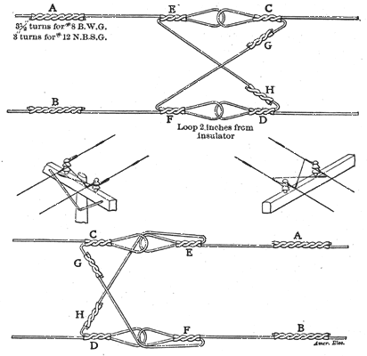
Whenever more than one telephone circuit is run upon the same pole-line over a great distance, the effects of induction from one circuit upon the others impair the service seriously. In towns and cities pole- lines are hardly ever long enough to be bothered in that respect, but the so-called toll and long-distance lines must be "transposed" to overcome inductive troubles. These transpositions are always made at the poles, using double insulators instead of the ordinary ones and dead-ending one end of the wire at the lower groove and the other end at the upper groove; then a cross-connection is made between the two sides of the circuit. Fig. 8 shows the regular transposition used for two adjacent insulators on the cross-arm where an unrestricted transposition can be made, and Fig. 9 the pole transposition necessary; the two insulators are located one on each side of the pole. Figs. 10 and 11 illustrate these transpositions with the insulators removed.
 |
| Fig. 8, 9, 10 and 11. — Regular and Pole Transpositions. |
The American Telegraph & Telephone Company specifies that these transpositions should be made as follows; Cut the wires on pole side 20 inches from the cross-arm. Slip on the half-sleeves C and D and dead-end as shown, leaving the ends projecting for sleeves G and H. Cut in 6 feet of slack on the pole side by means of the standard sleeves A and B. Slip the sleeves E and F on the slack ends and dead-end as shown. Sleeves G and H are then slipped on, and the transposition completed. Twist all half-sleeves 1 1/2 times. Hold the double connector at the insulator end of sleeves E and F, and at the wire end of sleeves G and H, stationary. In transposing pole wires, bring the cross-wire back around the glass as shown.
Fig. 12 shows in plan view the transpositions of ten circuits, five of which are on one cross-arm and the other five on the other cross-arm, the two cross-arms being designated as upper and lower cross-arm respectively. The twenty wires are numbered from 1 to 20, and each of the eighteen transpositions in the diagram is designated by a letter, beginning at the first transposition with A; C designates the third transposition, but the fourth transposition is designated again by B the same as the second transposition, because the fourth transposition takes place between the same wires as the second transposition. For the same reason, the fifth transposition is designated A again, and so on. When only one circuit is put up, the wires 5 and 6 are usually taken as the first circuit; the distance from transposition to transposition on this circuit is four times thirteen hundred feet or practically one mile. When the next circuit is added the transpositions occur every half mile, and so on according to the diagram. When the pole-line contains more than two cross-arms, transpose the third, fifth, seventh, etc., cross-arms like the first and transpose the fourth, sixth, eighth, tenth, etc., like the second cross-arm.
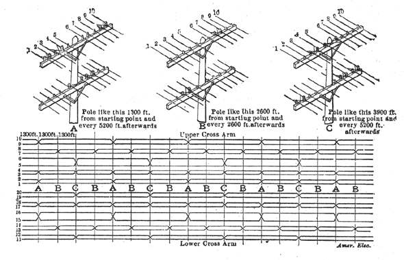 |
| Fig. 12. — Transpositions on Twenty Wire Line. |
Transpositions offer a convenient place where the line can be opened for testing, which is sometimes necessary when the line is found to be noisy. The tester will cut in on the line at each second transposition from the point he is testing with, as this would always be a balance point. In this way, he would soon find out the point where the unbalancing occurs and could clear the trouble by inserting another transposition in the center of the unbalanced section. In doing this, however, care must be taken that the circuit under consideration is not thrown out of balance with respect to the other circuits on the cross-arms.
