[Trade Journal]
Publication: American Electrician
New York, NY, United States
vol. 16, no. 4, p. 186, col. 2-3
SOME RECENT ELECTRICAL PATENTS
·
·
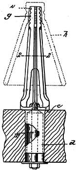
Insulator Pin. — With the view of producing a pin for supporting the large, heavy porcelain insulators now used for high tension transmission lines without involving the location on the cross-arms of an undue weight of material, James H. Bullard, of Springfield, Mass., has devised the form of pin shown by Figs. 3 and 4. The pin is to be made of cast metal, presumably steel, and the upper portion of it is of the cross- shaped cross-section shown by Fig. 3, which is taken on the line 2—2. The four vertical webs separate toward the bottom end of the pin, and their lower ends are united in a disc or plate, c, from the under side of which projects a hollow shank, d. Making this shank hollow confers two advantages: the pin is lightened and there is space for the retaining bolt, P, without having to drill through the shank. The bolt passes through the base plate, c, and is provided with the usual nut and washer at the lower end. The upper part of the pin is notched, as shown at g, but not necessarily in the form of a screw thread; it is contemplated to serrate the interior of the insulator at i, and to pour cement or molten metal into the insulator while the pin is in it, this cement or metal being intended to fill in the spaces between the webs and take hold of them and the insulator by filling also the serrations and notches. The inner "petticoat" of the insulator is indicated, of course, by the dotted figure, h. Patent No. 754,123.
 |
| Fig. 3. |
 |
| Fig. 4. — Insulator Pin. |
