[Trade Journal]
Publication: American Electrician
New York, NY, United States
vol. 16, no. 5, p. 245, col. 1-2
HIGH TENSION WALL INSULATOR.
In bringing high-tension lines into stations through the walls of the building it becomes a serious question how best to insulate the wires from grounding. In some cases the line is brought through a hole in the wall; in others, through an elaborate system of tubes placed in the wall; in others through a piece of insulating, material of some kind set in the wall; in others, the line enters through an elaborate tower built for the purpose on the top of the building; in still others it is taken directly through the roof of the building.
 |
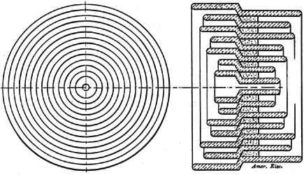
| Fig. 1. — High Tension Wall Insulator. |
It is manifestly impossible to prescribe any fixed method for all voltages and locations since this will depend upon a number of conditions. The requirements, however, that must be met are: The maintenance of proper insulation of the circuit; the prevention of the entrance of rain, snow, cold air and dust; the proper mechanical fastening of the line wire, and reliability and simplicity of construction.
In general, wires are best brought through the wall of the building. For high voltages a long insulating tube of small diameter and very heavy wall may be placed over the wire and passed through a slab of insulation set in the wall of the building, the whole being protected from driving rain by an extension of the roof. The insulating tube slopes downward and some form of drip point is provided on the wire just outside the end of the tube. This form of construction has been successfully used for potentials as high as 60,000 volts; but the chief difficulty has been to secure the proper insulating tubes, owing to the fragile nature of porcelain and glass, especially when only one tube is used.
 |
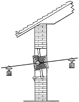
| Fig. 2. — Wall Insulator in Place. |
The Locke Insulator Manufacturing Company, of Victor, N. Y., has brought out the appliance shown by Fig. 1 herewith as a solution to the problem. This, it will be noted, is a sort of elastic affair, and can be built up of as many concentric tubes as may be necessary for the insulation of the voltage used. The maker claims that this nest of tubes when cemented together is very strong and substantial, so that fragility is not a part of its nature, and one of the objections lodged against insulators for the purpose under discussion, is overcome. The material used in its construction is a special mixture of clay claimed to withstand high working voltages, so that it combines insulating merit as well as strength. The method of mounting the insulator in the wall of the building is clearly shown in Fig. 2.
