[Trade Journal]
Publication: American Electrician
New York, NY, United States
vol. 17, no. 12, p. 603-608, col. 1-3
ELECTRIC TRANSMISSION AND DISTRIBUTION IN VERMONT.
HYDRO-ELECTRIC GENERATING STATION
AND SUB-STATIONS OF THE CH1TTENDEN
POWER COMPANY AT RUTLAND.
The Chittenden Power Company is about to place in operation its new power plant located about five miles from the City of Rutland, Vermont, one sub-station in the City of Rutland, and one sub-station at Castleton Corners, about 15 miles distant from Rutland, in a direction opposite from the power plant. The system will supply the Rutland Street Railway Company with power to operate the city railway line in Rutland, and an interurban road from West Rutland and Castleton to Fairhaven. Power is at present supplied from a steam generating plant located about midway between Rutland and Fairhaven. The situation of this plant is such as to necessitate considerable hauling of coal and other supplies, which with the present price of coal at Rutland undoubtedly means high generating cost. The building of the new plant was started last fall and it is just now receiving the finishing touches.
| |||
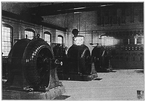
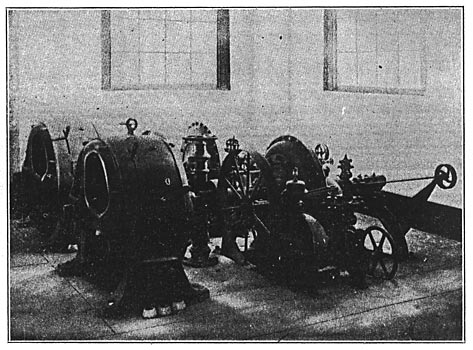
| Fig. 1. Interior of the Crittenden Generating Station Near Rutland, Vt. |
A reservoir is located above Rutland among the hills and an extensive dam with head-gates and spillway has been constructed at that point for retaining sufficient water supply to maintain continuous plant operation throughout the year.
Immediately above the reservoir which supplies the present plant is located a much larger reservoir, which can be developed later, and which will undoubtedly produce a greater quantity of power than the new plant does at present.
| |||
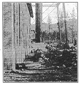
| Fig. 2. Pipe Line. |
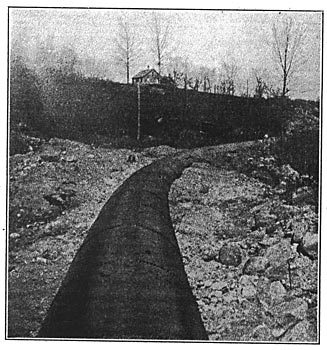
From the upper reservoir to. .the present reservoir, a 400-ft. head can be utilized. From the lower reservoir a pipe line 5 feet in diameter and 5000 feet in length, is carried down the valley to the new power plant, giving to this plant a head of somewhat over 200 feet. The 5-ft. pipe line is constructed of steel plate throughout, lap welded and double-riveted in all seams towards the latter end of the run, and lap-welded with a single row of rivets at the head of the run. Considerable excavation was necessary in order to properly install this pipe line, as the low temperature prevailing in this country during the winter months made it imperative that the complete line should be covered up.
| |||
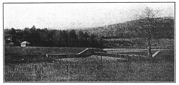
| Fig. 3. View of Power House Showing Water Tower. |
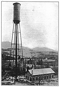
The power station is a brick structure with steel trusses and concrete slab roof. There are no purlines in the roof construction, as the slabs for the roof were moulded in forms set up on the ground, and after hardening were transported to the site of the power house a distance of about 300 feet; removed from the forms; hoisted to the roof and properly attached to the steel trusses. After being leveled the joints were pointed up with neat cement and a finished roof covering of roofing felt and an asphaltic compound installed. These slabs are 4 feet wide, 8 feet 6 inches in length, 3 1/2 inches in thickness, reinforced with 3 inches No. 10 expanded metal, and are composed of one part cement, 2 parts coarse, sharp sand and three parts clear, crushed stone, or gravel. Considerable gravel was used in the concrete work for foundations, floors and roofing for this building, as gravel was readily obtainable from the beds of two creeks which flowed one on each side of the power house. The sand for construction purposes was also conveniently located as a bank was found close to the power house site and on top of the hill. In order to utilize this sand it was only necessary to install a sheet-iron chute which deposited the sand at the proper location.
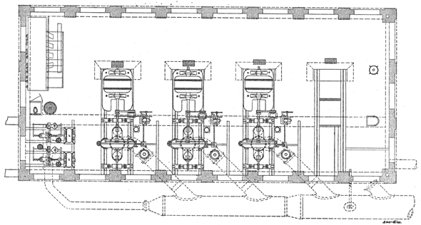 |
| Fig. 4. Plan View of Main Station. |
The pipe line is carried along the side of the building, and branches are taken in to four turbine wheels. A smaller branch is also taken in to supply two exciter wheels. Any of these branches can readily be cut out by gate-valves, which are installed on the branches close to where these enter the building. Pressure in this pipe line is maintained constant, and pounding or water hammering eliminated by the installation of a regulating tower 220 feet high having a tank of sufficient capacity to relieve the wheels of fluctuations in pressure in the pipe line.
The tank referred to is 16 feet in diameter and 50 feet high. It is built of bent steel plates properly riveted together, with a hemispherical bottom, also constructed of heavy steel plates properly riveted. A frost-proofing of wood encases the steel tank. The space between the frost-proofing and the steel tank is supplied with heat by a steam pipe running from a heater located in the power house to prevent freezing of water in the winter time.
| |||
| Fig. 5. Headgate and Spillway. |
The tank is supported on four lateral channel legs with sufficient struts and diagonal bracing to make a very stiff structure. Access to the tank from the ground is obtained by climbing the lateral braces on one of the columns. A circular platform surrounds the bottom portion of the tank. The run of the penstock is directly below and in line with the overhead tower. An 18-inch riser dupplies the tower with water. This pipe is encased within a 36-inch overflow pipe, which takes care of the fluctuations of the water lever, when suddenly shutting off or starting up the wheel. The space between the supply pipe and the overflow pipe is heated from the same system which heats the space between the steel tank and the frost-proofing.
The tail race is located immediately under the wheels and is carried about 150 feet beyond the power house, where it empties into the waste stream from the reservoir. It has concrete sides and bottom, and has a Weir plate installed outside of the power house for the purposes of measuring the water used.
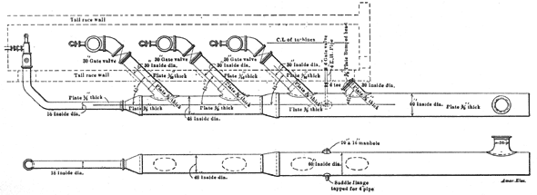 |
| Fig. 6. Detail of Penstock. |
The power house at the present time contains three 400-kw. revolving-field, alternating-current generators, with provision for the installation of a fourth unit. These are directly connected to three double discharge water wheels, which develop 770 horse-power at full gate opening. The wheels are enclosed in cast iron, manholes being provided for easy access to all parts, and supplied with 30-inch diameter supply pipe set to receive water from below. A 30-inch hydraulic valve controls the water supply to the wheels. All wheels are independently governed by Lombard type "F" governors. The generators are designed to run at 500 r.p.m., and to develop an e.rn.f. of 13,200 volts.
Two exciters of approximately 25 kilo-watts capacity are installed, and driven by small water turbines under the same pressure as the large wheels. Indicating devices for recording pressures and head of tail water, etc., are installed, and an indicating and recording tachometer is provided for each wheel; in fact, no pains have been spared to provide a hydraulic equipment which will be permanent, and insure satisfactory and cotinuous operation, under the varying conditions of load which are naturally met with in a railway installation.
| |||
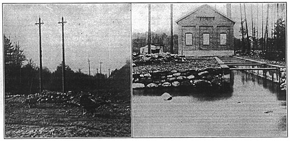
| (Left) Fig. 6. Transmission Lines (Right) Fig. 7. Rear View of Station Showing Tail Race. |
The switchboard to control this installation consists of panels for controlling the exciters, independent generator panels for each of the generating units, a regulating panel complete with automatic regulator for keeping the pressure constant at the delivery end of the transmission line, and two three-phase line panels. The generator and line panels are provided with high-tension oil switches mounted in concrete cell compartments and are hand-operated from the face of the switchboard.
All wiring for power in the building is encased in lead-covered cables, and has a working capacity of twice that under which it will operate. The power house lighting wiring is entirely encased in iron conduit, incandescent lamps being used throughout to facilitate the dismantling and repairing of machinery, the building is provided with a hand-operated overhead crane, and every means has been taken to insure easy operation and comfort to the operators.
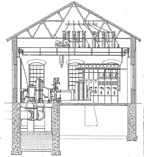 |
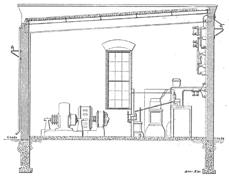
| Fig. 8. Sectional Elevation of Main Station. |
From the power plant two three-phase, 13,200-volt transmission lines are carried in an air line mostly on private right of way, to the Rutland sub-station, located near the center of the City of Rutland, and from this sub-station one three-phase transmission line is carried to the Castleton sub-station, located on the main street of Castleton Corners.
| |||
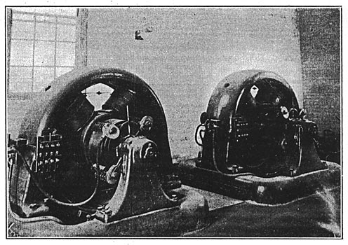
| Fig. 9. Turbine-Driven Exciter Units. |
These transmission lines are protected by lightning arresters, located within the buildings at each of the stations, and are so provided with high-tension switching apparatus, that either of the two transmission lines from the power house to the Rutland sub-station, can be used, or the two can be thrown in parallel. The switching apparatus in the Rutland sub-station has been installed so that the Castleton sub-station can be operated on either of the lines from Rutland to the power house, or can be disconnected from the main line and can be operated on the same lines with the Rutland sub-station, thus allowing entire flexibility of the transmission system, and eliminating all possible danger from interruption.
| |||
| Fig. 10. Penstock. |
The Rutland sub-station is a brick structure with a concrete roof, this roof being built in place. The building is located on property controlled by the Chittenden Power Company, and located in the vicinity of the company's gas works. The building is of adequate size to contain the present apparatus, and later addition of one unit making a total of three 150-kw. rotary converters. One side of the interior wall is devoted to high-tension switching apparatus and lightning arresters, in accordance with the above-described installation.
It is calculated that the transmission pressure at the entrance to this sub-station will be about 12,500 volts, which pressure is carried through high-tension oil switches, mounted in brick compartments, and thence to three 125-kw. air blast transformers connected in delta on the high-tension side.
| |||
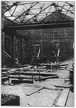
| Fig. 11. Main Station in Course of Erection. |
The low-tension side of these transformers is provided with double windings and connected in double delta, the secondary e.m.f. being 370 volts. These transformers are air-cooled and all wiring and connections on the low-tension side are in the air pits under the transformers.
The reactance coils are also air-cooled and are equipped with the necessary switching apparatus, for starting the rotary converters from the half voltage taps of the transformers, thus reducing the power consumption at the time of starting the rotaries, and allowing better regulation throughout the system.
| |||
| Fig. 12. Rotary Converters in Sub-Station. |
The low-tension wiring in these substations, as in the case of the power house, is lead-covered, but paper insulation has been substituted in the sub-station in place of the rubber insulation used in the main power house. All open, high-pressure wiring in the stations is rubber-covered. The high-tension oil switches are hand-oper-ated, from the high-tension line panel, which is also equipped with the necessary high-tension instruments.
| |||
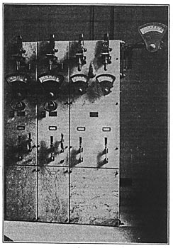
| Fig. 13. Sub-Station Switchboard. |
This sub-station, as before stated, contains at the present time two 130-kw. rotary converters, which converters are installed over the wiring pits. All wires and cables are carried from one piece of apparatus to another in camp conduit, laid in the floor of the buildings.
The rotary converters are each provided with a direct-current rotary panel and an additional line feeder panel for controlling the various railway feeders. This panel is equipped with the necessary indicating and recording instruments and lightning arresters.
 |
| Fig. 14. Sectional Elevation of Sub-Station. |
The transformers have duplicate blower sets, each of sufficient capacity to supply requirements, and each of these blower sets has its operating panel.
The Castleton sub-station building and equipment are the same in all general details as those of the Rutland sub-station, with the exception that the rotaries and their accessory apparatus are of different sizes, there being installed at the present time one 150-kw and one 200-kw. rotary converter, with adequate space for a future installation when conditions require it, of a further 200-kw. rotary converter.
| |||
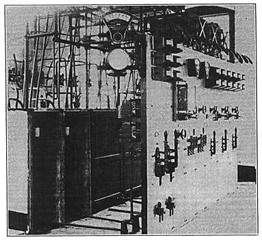
| Fig. 15. Switchboard in Main Station. |
The design of the entire system is such as to insure continuous and satisfactory operation under the worst conditions of load which are imposed by a railway system operating a city and interurban service. J. G. White & Co., of New York City, were the general contractors for the entire equipment and French & Bryant, of Boston, Mass., were the engineers for the Chittenden Power Company. The complete penstock work from the dam to the regulating tower and all the transmission lines were designed and installed by this latter firm.
