[Trade Journal]
Publication: American Electrician
New York, NY, United States
vol. 17, no. 9, p. 465-466, col. 1-3
The Electrical Equipment of the American Thread Company
BY GEO. A. BURNHAM.
The hydro-electric plant of the Willimantic Mills of the American Thread Co. presents several unusual and interesting features in its electrical equipment. The plant is situated on the banks of the Willimantic River, from which a portion of the power consumed is taken. The flow of water is comparatively swift and varies within wide limits during the different seasons of the year.
| |||
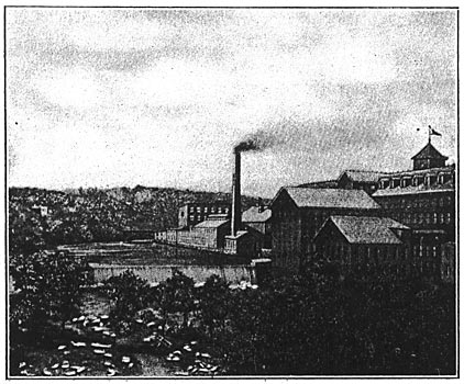
| Fig. 1. Dam Across the Willimantic River. |
The intakes to the water-wheels are from three different dams located about 500 feet apart. These dams are of solid stone masonry, and the material for construction was blasted from the river bed.
The available horse-power of dam No. 1 is 950 horse-power ten months in the year and 350 horse-power twelve months in the year. The water from this dam is diverted into a canal 17 feet wide, 10 feet deep and about 600 feet long, from which it passes through an 800-h.p. horizontal turbine and is discharged through the tail race in the river below dam No. 1.
| |||
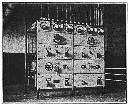
| Fig. 2. Switchboard. |
The water which is utilized in the 800-h.p. turbine, together with that which flows over dam No. 1, is backed by dam No. 2, of which the available power is 300 horsepower twelve months in the year and about 350 horse-power ten months in the year. The water diverted by this dam is passed through three 250-h.p. vertical turbines and discharged into the river below, to be again utilized by two 75-h.p. vertical turbines located at dam No. 3. The average total available water-power is about 1100 horse-power yearly. The total power consumed is about 3000 horsepower, of which 1100 horse-power is derived from water and the remainder is furnished by steam. A view of dam No. 2 and a portion of mill No. 2 is shown in Fig. 1.
Although contrary to modern practice, the generating units, instead of being grouped in one central station, are spread out through the various mills, and in each case driven from the main shaft or the water turbines. This arrangement gives a very flexible and reliable system; also provides a way to utilize the surplus water, which would otherwise have been wasted over the "spillway," by converting it into electrical energy and transmitting it to the mills which are operated by steam.
The electrical equipment throughout was manufactured by the Stanley-G. I. Electric Manufacturing Company, of Pittsfield, Mass. The generators and synchronous motors are all of the inductor type, two-phase, 60-cycle, and operate at 2,350 volts.
The main station is located at mill No. 2 and contains a 300-kw. and a 100-kw. alternator, the fields of which are excited by two 125-volt, direct-current generators of 9 kw. and 7 kw capacity; a 45-light Brush arc machine, with its plug-board, and the main distributing board from which all circuits are controlled and to which all feeders from the outlying stations are connected.
The switchboard consists of two panels of blue Vermont marble, seven and one-half feet high, two inches thick, mounted on heavy steel angle bars. The panels are "built up" of five sub-panels each four feet long and eighteen inches wide. On the back of the board are supported two sets of bus-bars, one connected to the 300-kw. machine and the other to the feeder of all the other stations, and also to the 100-kw. machine located in the main plant. Four switches at the base of the board control the entire output of the plant. Two sub-panels carry the field switches and also the field and exciter rheostats. The field switches are of the double-pole, double-throw type, which enables either of the two exciters to be used to excite either of the fields of the two generators.
One panel supports the two main switches which connect the 300-kw. machine to its bus-bars, and another supports two switches which were originally designed for main switches of the 100-kw. machine, but are now used to tie the feeders of the outlying stations to the feeders of the 100-kw. generator located in the main plant. These two sets of switches are of the combination-slide switch and circuit-breaker type. Two static ground detectors and two voltmeter switches, by means of which the voltmeters may be connected to either phase of the system, are mounted on a panel, on which are also located the synchronizing lamps and plugs.
 |
| Fig. 2a. Diagram of Switchboard Connections. |
The top panel is somewhat narrower than the others and carries the measuring instruments, whose dials are illuminated by four double-armed pilot lamps. On the adjacent panel are located two ammeters and a voltmeter. A duplicate set is also provided on the other panel. These instruments indicate the total output of the station. The board as a whole presents a very neat appearance, being very compact and yet having ample room for the proper spacing of the wires. Fig. 2A is a diagram of the switchboard wiring, while Fig. 3 shows a diagram of connection for the feeders from the outlying stations and the switching apparatus on the main switchboard.
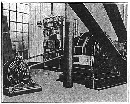
Plant No. 1 is located at mill No. 1 and contains a 100-kw. alternator and a 2-kw., 125-volt, direct-current generator used as an exciter. The switchboard is of the skeleton type and is equipped with circuit-breakers, two ammeters, static ground detector, power factor indicator and the usual synchronizing appliances. Fig. 4 shows the generating outfit. This machine is used through the day to transmit power to the steam-driven mills, and during low water is used as a synchronous motor, taking current from the generators below the No. 2 dam or the steam-driven units.
 |
| Fig. 3. Diagrams of Connections for Feeders From Outlying Stations. |
Plant No. 3 is located at mill No. 3 and consists of a 40-kw. generator and an exciter of 1 1/2-kw. capacity. This machine is driven by water-power and is used exclusively for lighting, but may be thrown in parallel with the whole system.
| |||
| Fig. 4. Electric Generating Outfit in Mill No. 1. |
Plant No. 4 is located at mill No. 4, and the generator, which is a 120-kw. machine, is driven from the main jack-shaft of the mill. The field of this machine is excited by a 2.62-kw., 125-volt, direct-current generator. The switchboard is of the skeleton type and is a duplicate of the board at mill No. 1, with the exception of the power factor indicator. This plant is steam-driven and is only operated during dry season to help out the other mills; at other times this generator is used as a synchronous motor, current being taken from the water-driven plants.
The building of a pole line to support the conductors from the various mills was a rather serious problem. The character of the soil about the mills is very rocky and in most cases solid ledge, making the construction of an ordinary pole line out of the question. This naturally resulted in placing the wires on the mills, but this has also entailed other difficulties owing to snowslides and dropping icicles, which formed in abundance during the winter months. The difficulties were overcome by several simple protective devices. The cross arms were made of 6-in. channel irons. The pins were also made of iron and bolted to the face of the channel irons, which were attached to the stone buildings by means of expansion bolts. Fig. 5 shows the method of attaching the pin to the arm. Insulators tested to 5,000 volts were used throughout the line construction. This method provides a very rigid support for the wires, and no trouble has been experienced with the arrangement.
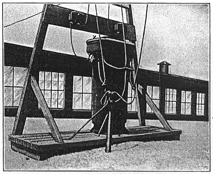
The transformers are of Westinghouse, Stanley-G. I. and General Electric makes of the following sizes: Three 40-kw., two 25-kw., six 15-kw., five 10-kw., and several others of smaller sizes. The primaries of these transformers are connected to the middle and outer wires of a three-wire, two-phase system, and are arranged in such a manner that the load at all times is nearly balanced. Fig. 6 shows a view of one of the 40-kw. transformers, installed on the roof of mill No. 4. The secondaries of these transformers are connected to the three-wire distribution which is used throughout the mills.
 |
| Fig. 5. Method of Attaching Pin to Arm. |
Forty Couch & Seeley inter-communicating telephones are installed in the mills, in addition to several other private lines. The cables are of the paper insulated type, enclosed in a lead sheath. Branches from the main cable are all made from junction boxes, by means of which the system may be divided into six separate systems. This division makes the locating of cable trouble very easy.
| |||
| Fig. 6. Transformer Arrangement on Roof. |
The engine and water-wheel rooms are all equipped with emergency stop signals, and a separate system is installed for starting and stopping. The watchman's clock system is of the battery type and consists of about two hundred stations. The signals are recorded on a four-dial clock situated in the main office. The system of electrical distribution was designed and installed by the writer.
