[Trade Journal]
Publication: Electrical Review
New York, NY, United States
vol. 8, no. 19, p. 1-2,3,6,7, col. 1-4,1,2
LONG DISTANCE TELEPHONING.
THE EXPENSIVE ENTERPRISE THAT THE AMERICAN TELEGRAPH AND TELEPHONE COMPANY WILL SOON HAVE COMPLETED — DETAIL OF THE LINE AND CABLE WORK.
The American Telephone and Telegraph Company, of this city, is a corporation organized by the American Bell Telephone Co. for the purpose of placing the large cities of the country in prompt and satisfactory telephonic communication, the first complete system having been constructed between New York and Philadelphia, a distance of 100 miles. There has been expended by the company, up to the present time, over $200,000, which can be taken as an evidence of the faith the promoters of the plan have in the success of the enterprise The president of the "long-distance" telephone company is Mr. T. N. Vail, and the general manager is Mr. E. J. Hall, Jr., formerly of the Buffalo Telephone Company. The work has been done under the specifications of Mr. T. B. Doolittle, of the Bell Company.
In the intricate and delicate work of testing every line and cable, aud discovering and locating, all, escapes and slight defects, General Manager W. D. Sargent, of the New York and New Jersey Telephone Company, has been of invaluable assistance to the company. In this work he was ably assisted by electrician John Barrett, of Brooklyn. The General Superintendent of Construction of the American Company is Mr. W. H. Fairbanks, an experienced telegraph construction man, whose work has been most satisfactorily done.
The history of the inception and gradual advance of this development of the telephone is replete with interest. The first attempt to connect Eastern cities by telephone was made some four years ago by a company known as the Inter-State, which constructed an iron wire between New York and Boston, which failed, however to work satisfactorily. Two years ago the American Bell Company erected a metallic circuit of hard-drawn copper wire on the poles of the Inter-State Company, for the purpose of testing copper wire for long-distance use. The experiment with the Blake transmitter demonstrated that this wire would work satisfactorily electrically, and then followed tests for discovering the best method of manufacturing the wire so that it would stand. The result of all this pioneer work was the organization of the company, as stated, above, with means and ability to push the work rapidly and intelligently The present construction extending between New York and Philadelphia was begun in August, 1885, When the wires were strung, the very important question as to whether there would be cross-talk between the metallic circuits was answered — and in the afiirmative. This had to be over-come, for the promoters of this work realized that there should not be the slightest noticeable induction or interference if the long-distance telephone work was to attain the magnitude intended and secure the popularity necessary to make it a commercial success. This result, after much experimenting, was secured by an arrangement of the wires that secures an electrical balance between the circuits.
It will not be out of place to state here that every individual connected with the construction has had a personal interest in it, and all are entitled to considerable pride in the electrical and mechanical success of the venture, as now proven. A new era in business transactions between cities is now to be introduced, and while it is not wise to predict, yet it would seem that its success commercially is only a matter of a few weeks' time, which will see the Philadelphia system connected with these long-distance cables, which are now asking for entrance into that city.
THE POLES AND CROSSARMS.
The poles and crossarms were carefully selected and rigidly inspected, and the utmost diligence was observed in carrying out Mr. Doolittle's specifications relating to the construction. The poles are chiefly of chestnut, 45 to 70 fefet in length, seven inches at the top, secured by a substantial iron ring with a heavy top pin, to which is attached a No. 8 iron guard wire. Seven gains are cut in all of the poles, three of which are occupied by ten pin cross arms. 3 1/4 x 4 1/4, braced the entire length of the line from New York to Philadelphia with the Haskin's brace. The poles are planted at a depth of from six to eight feet, pointed at the bottom. The guy wires are of wire rope, anchored to large boulders buried deeply in the ground. The insulators are known as the "screw top," and the pins of split white oak timber.
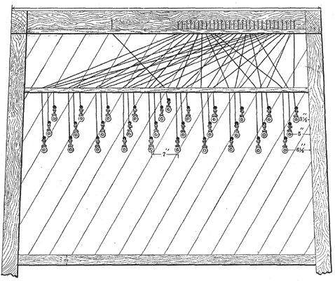 |
| Fig. 1. — Interior View of Section of Cable House, Showing Method of Attaching the Wires. Adopted by the American Telegraph and Telephone Co. |
THE WIRES.
There are at the present time twenty-four hard-drawn copper wires strung the entire distance of 100, miles, making a total length of 2,400 miles of copper wire. The sizes, are Nos. 12, 14 and 16, new British gauge, the different sizes being put up for the purpose of securing a practical test of their respective merits. The outlay for the wires alone has been a very great sum, but no cheaper wire was considered, as the advantages of hard-drawn copper for long-distance work has become too well-known to admit of any other kind being thought of for such an important work.
THE CABLES.
Between the cities of New York and Philadelphia six series of submarine cables are used in the various rivers, amounting to a total length of twenty miles of seven-wire kerite cables. These cables were specially manufactured for this work by Day's Kerite Company, the longest stretches of cable being required to cross the North and Delaware rivers. These cables terminate at the foot of Vesey street, in New York, and at a point near the foot of Walnut street, in Philadelphia. From the New York landing the wires are carried to the central office on Fulton street by serial cable from the same manufactory, this office being connected with the New York telephone system.
THE CABLE HOUSES.
These are of novel and most convenient pattern, framed of wood, with bias sheathing covered with waterproof paper, and clap-boarded over all. With their shingled-hipped roof they are as impervious to water as a dwelling house.
There are two stories or floors, the first, about five feet in the clear, used for the storage of materials, etc., and the second about seven feet. The second floor, of which we give a side view in Fig. 1, is reached by a vertical ladder through a trap-door, and here, high and dry, are located the lightning arresters, wires, etc. Near the center of this space is an upright framework, covered with matched sheathing, upon which the lightning arresters are fixed. To the right of the arresters is placed a telephone set for the inspectors use in testing the wires, shown in Fig. 3 on the following page.
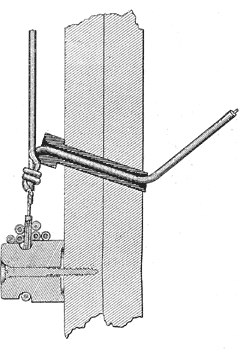 |
| Fig. 2. — Enlarged View of Single Connection. |
A shelf is fixed at a convenient height, upon which are arranged a row of cords, plugs and weights, for the purpose of connecting the telephone set, and for cross-connecting or "patching up" wires in case of trouble.
A long slot is cut in the sheathing back of the lightning arresters, which emits light from the window, and enables the inspector to discover any trouble which may have arisen from a heavy discharge or other cause.
Kerite or okonite-covered wires are taken in regular order from the lightning arresters and carried over the top of the frame by the side of the house, and then taken through cleats to their proper positions on porcelain insulators, which are arranged on the inside of the houses, and sufficient quantity of wire is wound around itself — section view of this is seen in Fig. 2, at top of insulator — to serve for future needs. Covered wire is brought from the line through rubber tubes, set at an angle in through the side of the house. A sectional view of tube is shown above. They are then brought down to a point just above the porcelain insulator, when the inside wire is bared and a connection is made. This connection is afterwards covered with kerite tape, therefore it will be seen that there are no uncovered points for escape except the rubber surface of the lightning arresters, and the favorable position of those eliminates any danger at that point.
There are three windows, one on either side, and one directly behind the lightning arresters, for the purpose described above. The windows are protected by hinged battened blinds, which close tight and are securely bolted.
The floor space inside is 7x7, making a snug little room.
THE LIGHTNING ARRESTERS.
The copper conductors, of which the line wire is composed, afford an excellent thoroughfare for heavy electrical discharges. Therefore the lightning arresters, at the cable houses, have been designed with special regard to the extraordinary work which they have to perform, and the detail of their construction presents many novel, interesting and valuable points.
A glance at the engravings, on pages 2 and 3, and 6 and 7, with the following brief description, will enable our readers to fully understand these peculiarities.
The arresters are constructed in groups of ten, and so arranged as to be conveniently joined together to an unlimited extent. The backboard is an oblong mahogany frame upon which are screwed firmly two hard rubber plates one-quarter inch in thickness, shown in black in the cross section. Fig. 6. Upon these plates are placed the heavy brass mountings to which the line and cable wires are attached. By this means the leakage caused by the absorption of moisture by the wood (as in the ordinary method) is avoided. The leakage must come exclusively from the surface, which is ordinarily dry.
A fine galvanometer test shows no escape, but a breath on the surface will deflect the needle. A heavy brass "ground bar passes down the center, to one side of which is presented the line points in the form of saw teeth. This bar is connected to the ground by a very large copper wire. These points are also very heavy and are intended to afford protection from the outside line, by furnishing ample means of escape for heavy discharges as well as to relieve the fuse wire from overheating.
The fuse wire is of soft silk-covered copper .008 inch diameter, and coated with a solution of "okonite." This wire shows an insulation of one-half megohm per 1,000 feet after 20 hours immersion in water.
One end of the fuse wire is attached to the screw head on line point, then passed once around the brass stud in the "ground plate," and separated therefrom by paraffine paper, then passed under the screw head on the cable point and drawn taut.
The line points are in two pieces, and are connected by a screw plug (shown in Fig. 7), which provides an excellent electrical connection, and is an absolute guard against "working loose " or dropping out as in the case of taper plugs.
The plugs are provided with a coarse thread, consequently the same amount of turning required to set a taper plug will send them home.
This arrangement of arresters is free from the defect common to nearly all that have an obscure un-get-at-able point to be neglected or overlooked by the inspector. A glance will suffice to detect any trouble with the system.
The removal of the screw plug opens the line, and the holes drilled and tapped in both the line and cable points (indicated in the arrester cut) enable tests to be made in either direction instantly and without disturbing the wires.
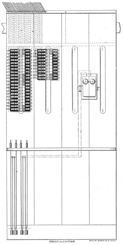 |
| Fig. 3. — Showing Arrangement of Lightning Arresters in the Cable Houses of the A. T. & T. Co. |
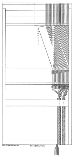 |
| Fig. 4. — Sectional View of Arrangement of Lightning Arresters and Wires. |
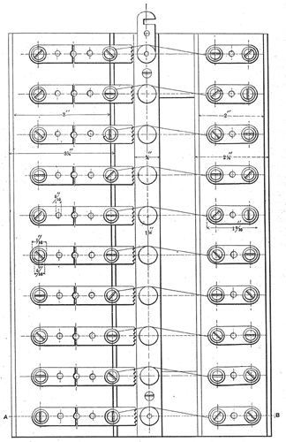 |
| Fig. 5. — Group of Lightning Arresters, As Arranged in the American Telephone and Telegraph Company's Cable House. |
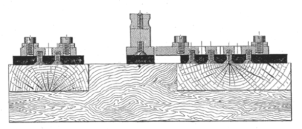 |
| Fig. 6. — End View of Section A to B of Fig. 5. |
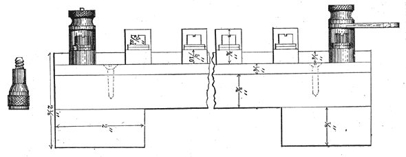 |
| Fig. 7. — End Elevation of Lightning Arresters, Showing Connection Screw. |
