[Trade Journal]
Publication: Electrical World
New York, NY, United States
vol. 4, no. 14, p. 124, col. 2-3
Self-Binding, High-Resistance Insulators.
Last April we published a brief but interesting article from Mr. J. F. Kelly, on the subject of porcelain insulators, and mentioning the Lewis self-binding insulator as worthy of more than passing attention. This form of insulator appears to have made great way in England in public favor, and Mr. J. Slater Lewis, of Birkenhead, England, is now in this country to represent the interests of the Patent Self-Binding Telegraph Insulator Company (Limited), a corporation controlling the patents under which his insulators and accompanying devices are manufactured for telegraphic, telephonic and electric light purposes.
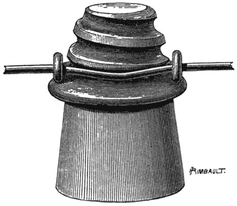
We illustrate on this page two of the methods of binding in connection with the Lewis insulator, which, it may be well to mention, though preferably of porcelain on account of superior resistance, can also be if required of glass or stoneware. These insulators made in the general style to which we are accustomed here, dispense with the familiar and inconvenient methods of binding by reason of their special and peculiar details. The line wire, as Fig. 1 indicates, is applied instantly without the use of any tools whatever, in any desired position. The binding is effected by hooking on the line a rigid galvanized iron or steel clip resembling a horseshoe in shape, and by inserting therein the large conical screw formed on the top of the insulator — the clip and the screw thread being adjusted in manufacture to each other. As the thread increases in diameter from bottom to top of insulator, on giving the latter a few turns it becomes rigidly fixed in its position, and the wire is held in a deathlike grip by the hooks of the tightened clip. The insulator itself can be mounted on a suitable bolt-pin or bracket. Friction and chafing are entirely avoided by these means, while cut or broken wires are prevented from "running back." It will be seen that there must be a great saving of time, and another recommendation is that any gauge of wire can be held, whether the line is tightly stretched or loosely. The clip may be dispensed with, and the line firmly bound in with stout wire, or it may be doubly bound with ordinary binding-wire, and even soldered fast. Notwithstanding this, the Insulator may be detached and re-attached instantly, without disturbing the binder. This latter method, however, is only recommended in very exceptional cases, where hard drawn copper or silicious-bronze wire is used.
 |
| Fig. 1. |
The insulator is kept free from the usual streaks of rust I which follow as the result of the binding-wire having its coating of zinc cracked off in the process of wrapping or lashing it round the line-wire, by reason of the clip which encircles the insulator being wholly galvanized and undamageable, and in consequence of the total absence of friction and "working" of the wires.
The resistance of the ordinary insulator is considerably diminished through such amass of thin binding-wire being in absolute contact with the glass or earthenware, forming a great number of small receptacles and crevices which serve to retain damp and dirt whereas, in the Lewis self-binding insulator, the line-wire and clip only touch at three points, thus raising the insulating qualities of the system far beyond the ordinary kind. It has also shown that oxidation and an injurious chemical action take place more where the binding-wire is wrapped round the line-wire than at any other point, and that, in consequence, breakages occur more through that defect than through any other cause.
 |
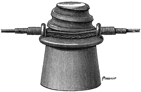
| Fig. 2. |
Fig. 2 shows a supplementary form of binding for crossings, streets, roads and house-top work. The method is this: Two lengths of No. 16 galvanized iron wire, each two feet in length, are placed side by side, and twisted four or five times round each other in the centre. They are then bent into the shape of a long U. The two ends on both sides are then passed underneath the line wire, between the head of the insulator and the hook of the clip. The wire is then pulled through until the twisted portion is fixed, as shown in the cut, close underneath the line. One wire on each side is then twisted round the line for about 1 1/4 inches on the outsides of the clip, the two remaining wires being twisted in a reverse direction over the first wires, in the manner illustrated.
It would seem that this system, which is practically adaptable to all forms and sizes of insulators in glass or porcelain, has considerable merit; and as in this country a good thing never goes begging for patronage, these self-binders will soon become extensively used.
