[Trade Journal]
Publication: Electrical World
New York, NY, United States
vol. 5, no. 3, p. 25, col. 1-3
Overhead Telegraph Wire. — Part V.
BY WM. MAVER, JR.
During the process of drawing iron and copper wire, it is essential that the wire be frequently gauged. Especially is this true of copper wire, and in well-regulated establishments a man is generally deputed to make measurements of the diameter of the wire as it comes through the die. This is essential, because, from some of the causes already alluded to, the die may become choked up or cut out, and thus a wire of very uneven diameter would be the result.
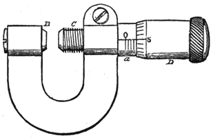
Various forms of gauges for measuring the diameter of wire are employed, but the one most frequently used now is that shown in Fig. 10, called a pocket micrometer gauge. The method of using it is as follows: The wire to be measured is placed between B and the screw C; C is a continuation of the socket D. This socket, or cylinder D, slides over another socket a, through, which the screw C runs; a is securely fixed to the U-shaped holder; D is beveled at one end, and this end is graduated into parts, calibrated 0, 5, 10, 15 and 20. The socket a is also graded, as shown by the perpendicular lines. The distance between any two of those lines is the 35 one-thousandths of an inch — that is, the one fortieth of an inch. The screw C has 40 threads to the inch. When the socket D has been revolved so that the gap now shown between B and C is closed, the graded line under O on the socket a is just covered by the socket D. The screw C being a part of the socket D, of course revolves with it. When the screw is given one complete turn, it will open a space between B and C of one-fortieth of an inch, and the first perpendicular line from O on a will be just covered by O on the beveled edge of D. The fractional part of a revolution of the screw to the one-thousandth of an inch is indicated by the horizontal lines on the edge of D.
Thus, when the screw C is brought out until it stands in the position shown in the figure, a wire fitting between B and C would have a diameter of 80 thousandths of an inch.
The result is reckoned in the following manner: We can see that there are, counting from O on a, four perpendicular lines uncovered; this indicates three revolutions of the screw C, and as each revolution equals 25 one-thousandths of an inch, we thus get 75 one-thousandths of an inch; but the screw has moved more than three revolutions, as shown by the fact that the 5 one-thousandths line on the beveled edge is opposite the horizontal line O. This is added to the 75one-thousandths, making the diameter of the wire inserted as above.
The dies are measured by using a piece of wire of the desired diameter, which is inserted in the die. Should the die be too large, it is battened with a hammer; if too small, it is reamed out.
 |
| Fig. 10. |
When the process of drawing wire was first adopted, the number of the gauge of a wire was indicated by the number of times the wire had been drawn through the dies. For instance, if it required ten drawings to bring a wire to a certain diameter, the gauge of wire of that size would be No. 10. It thus came about that the thicker the wire, the lower the number, and vice versa, and as wire of even a greater diameter than No. 1, became, for certain purposes, a necessity, the sizes were designated by ciphers until there is now a gauge of five noughts.
There are various wire-gauges in vogue; for instance, the Birmingham, the American and the London. Some of these gauges are arranged on a regular plan, for example, a geometrical progression in which each size is 20 per cent. more or less in weight and electrical conductivity than the size immediately preceding or following it. Others are arbitrary; that is, a manufacturer has decreed that No. 12 gauge will be 109 thousandths of an inch in diameter; that No. 14 will be 83 thousandths of an inch, etc.
A specimen of the latter is the Birmingham wire gauge, which is somewhat widely used in this country, and if it or some other particular gauge were entirely used, it would be very advantageous to all concerned; but such is anything but the case. In fact, every manufacturer has his own gauge, and thus by one standard No. 12 represents a wire 109 thousandths of an inch in diameter, while by another the same number of gauge will signify a wire 104 thousandths.
It is thus rendered necessary to add in almost every case the name of the gauge when ordering wire, or to designate the wire by its diameter regardless of gauge. Many attempts have been made at different times and by different persons to secure uniformity in wire gauges, but without success.
At the last meeting of the Telephone Exchange Association, a committee of three was appointed to endeavor to bring about such a result, and it is-to be hoped they will succeed.
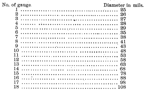
In this relation it has been suggested that inasmuch as, from one cause or another, previous attempts to secure an uniform gauge have failed, a plan might meet with approval in which some sweeping change should be proposed, such, for instance, as to completely turn around the present systems in which the larger wires have the lowest numbers, and to begin at No. 1, giving it the diameter of the finest wire possible to make, and then number each succeeding diameter by a regular increase of one or more thousandths of an inch, or still less if required, up to a certain point, when the increase could be made greater, and so on. For example, assuming that a wire having a diameter of 25 mils (a mil being the one-thousandth of an inch), is the smallest wire drawn, it would be called No. 1 of the new gauge, which would give us a table somewhat as follows :
 |
Of course, the above ratio of increase is given merely for the sake of illustration. In the event of the adoption of an arrangement in any way similar to the foregoing, the needs of the trade would be taken into consideration by the formulators of it.
 |
| Fig. 11. |
A proposition was recently made to adopt a gauge for telegraph wire having for its basis the weight of the wire per mile. This suggestion would be a good one but for the fact that all metals do not weigh alike, and consequently the diameter of an iron wire of a certain gauge number would not correspond with that of a copper wire of the same number, which would entail confusion.
After all the foregoing tests of the wire have been made, each coil is again inspected, previous to weighing off, to detect, in the case of iron wire, any imperfect galvanizing that may have escaped notice on the first inspection.
The wire is then considered ready for final inspection by the purchaser, who, as a rule, sends his own examiner to inspect the wire thoroughly before accepting it, after which, if the results are satisfactory, the wire is then shipped to its destination, where the test of its qualities begins in earnest.
Every bundle or coil of copper wire intended for overhead purposes is, or should be, covered with paper or matting before shipping, as the handling and jolting received in transportation, and the consequent wrinkles and kinks, would otherwise lay the foundation for numerous future breaks.
As previously intimated, I shall now give some of the actual results obtained with hard-drawn copper wire as an overhead telegraph wire.
In the spring of 1884 the Baltimore & Ohio Telegraph Company began the erection of two lines of No. 14 B.W. G. hard-drawn copper wire between New York and Chicago. This wire weighs 110 pounds per mile, has a breaking strain of 350 pounds, and an electrical resistance of 8.50 ohms, about equal to a No. 6 iron wire weighing 572 pounds per mile.
At the commencement of the erection of these wires, one very fertile source of trouble was a lack of acquaintance on the part of the linemen with the characteristics of hard-drawn copper wire. The men having been accustomed to handling the much heavier and more tenacious iron wire, would thoughtlessly kink the copper wire, and in tying it around the insulators would give it a bend that, by almost cutting it, made bad and discouraging work with the first 40 or 50 miles erected, and breaks, seemingly without cause, were of frequent occurrence.
A prompt and searching investigation, however, speedily showed that, in almost every case, the breaks were due to ignorance on the part of the linemen and also to a weakening of the wire by heating at the joints.
These faults were at once rectified, and the remainder of the wire, owing to its lightness, was erected with less trouble than the adjacent iron wires, and with no apparent liability to breaks from above-named causes.
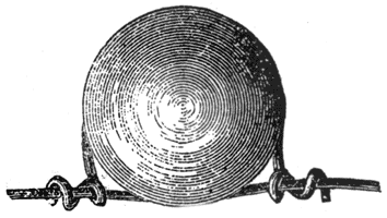
A top view of the old method of tying the wire to the insulators is shown in Fig. 11. The tendency, as I have said, in tying the wire in this way, is to chafe and cut the line wire at the point nearest the insulator. With care, however, this fault has been almost entirely overcome.
Other methods of tying and protecting the wire have been tried with varying degrees of success, one of which was to insert over the wire, at the insulator, a copper sleeve, about 6 inches long, around which the tie wire is wound. This has the disadvantage of being an expensive plan.
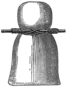
Another plan, and the one which is now recommended by the different superintendents of construction, and which will very likely be generally adopted hereafter by all companies using hard-drawn copper wire, is shown in Fig. 12. It will be noticed that by this arrangement of the tie wire there is no undue strain on the line wile, and that, while it is quite sufficient to hold up the wire, it still permits it to slip through the tie; which is an undoubted advantage, inasmuch as this allows safe play, as it were, in case of contraction by cold, and spreads the strain along a consider able length of wire, and thus advantage is allowed to be taken of any slack that may exist between some of the poles.
After many experiments with different form of joints this company has adopted a joint devised by Mr. John A. Helvin, superintendent of construction, which has been found to meet nearly all the requirements. It consists of a cylindrical brass sleeve, about one inch long, through which two parallel holes are bored, into which the ends of the wires to be joined are placed. The wires are then lapped around each other four or five times and soldered lightly at the ends of the sleeve. This form of joint has been found to possess a higher tensile strength than any other form of joint tested, breaking at almost the same strain as the wire. Having around surface, it offers less opportunity for retaining the wires when they may happen to swing together — a good feature.
These wires have now been on the poles and in constant operation for over eight months, giving continual and exceptionally good service, and owing to their small surface area it has been found quite possible to work duplex systems on them from New York to Buffalo, and Buffalo to Chicago, without any electro-static compensation whatever. It has also been found that these wires are not so subject to breaks from sleet and soft snow as the larger iron wire, which is probably due not alone to their smaller surface, but also to their much smoother surface, which prevents the rain from lodging thereon.
In addition to the above-mentioned wires, the same company has just completed a No. 14 hard-drawn copper wire from St. Louis to Texarkana, Ark. — 570 miles — for Texas business.
During the late severe cold snap, when the thermometer fell from 30° above to 20° below zero in the Mohawk Valley, in one night, much anxiety was felt as to the effect on the copper wires, but investigation showed that the percentage of breaks on these wires was slightly less than that of the No. 6 and 8 iron wires strung on the same poles.
 |
| Fig. 12. |
Altogether, the results of the use of hard-drawn copper wire by the Baltimore & Ohio Telegraph Company, which, as I have already said, was the first telegraph company to go into the extensive use of this metal for this purpose, have been very satisfactory and have fully demonstrated the wisdom of the policy that inaugurated its use.
That this is so must be evident from the fact that after an eight months' successful trial of 4,500 miles of No. 14 hard-drawn copper wire, this same company has just begun the erection of 3,000 miles of hard-drawn copper wire having a diameter of 104 thousandths of an inch, weighing 170 pounds per mile, with a breaking strain of 550 pounds, and an electrical resistance per mile of 5.3 ohms, equal to a No. 3 iron wire; from which even better results are confidently anticipated.
Reports received from the copper wire in use for telephonic purposes also show favorable results, all of which would seem to verify the prophecy made by Mr. W. H. Preece, of England, before the recent Conference of Electricians in Philadelphia — in which prophecy he was, however, anticipated some twelve months by Mr. D. H. Bates, President of the Baltimore & Ohio Telegraph Company — namely, that the days of iron wire, as an over-head conductor, were numbered.
