[Trade Journal]
Publication: Electrical World
New York, NY, United States
vol. 6, no. 10, p. 99-100, col. 1-3,1
The Daft Electric Motor on the New York
Elevated Railroad.
It may be safely asserted that no engineering event within the last few years has attracted popular and professional attention more than the present trial of electricity as a motive power on the elevated railways of this city. The daily papers have printed columns regarding the event, and a number of illustrated papers have produced illustrations of the motor which is now upon the tracks.
Before entering into a description of the system, as it is operated, it may be well to recall the events which have led up to the present state of affairs.
The idea of running the elevated railway trains by electricity was broached several years ago, the many strong points in its favor, over steam, being pointed out. Nothing, however, was done in the matter beyond its mere discussion, until the early part of this year, when at a meeting of the various electric motor companies, an attempt was made to consolidate their interests, and to test the motors of the various companies represented. A commission was to be appointed (Sir William Thomson being designated as one of them) to test the motors, and the best system was to be adopted. Several meetings were held, but the scheme finally fell through. This agitation acted as a stimulus, however, for shortly afterward the Daft Company obtained permission to equip a section of the Ninth Avenue Elevated Railway on its system, while the Edison-Field interests were assigned, to the Second Avenue road.
From that time until now, a period of six months, the Daft Company has been busy equipping a central station, building a motor and laying down the central rail required. It must be understood that the latter operation had to be performed during regular traffic hours, with trains passing every five minutes or less.
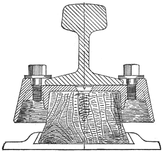
The road is equipped from the elevated railway station at Fourteenth street, up to Fifty-third street, a distance of two miles, in which a heavy grade is encountered. The central rail, through which the current is led to the motor, is elevated above the outer ones, resting upon the insulator shown in Fig. 3.
 |
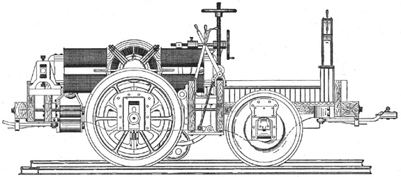
| Fig. 1. — Elevation of Daft Electric Motor "Benjamin Franklin." |
The central station, in which the generating dynamos are placed, is situated in Fifteenth street, a distance of about 250 feet west of the tracks, and connected with the latter by a stout conductor. The station contains a Wright steam engine and three generators. In addition, there is a small dynamo which runs the Daft arc lamps, by which the station is lighted at night.
The motor now upon the tracks is named "Benjamin Franklin." It was on the night of Wednesday, the 26th inst., that the first run was made. This, however, was only for the purpose of cleaning the rust from the central rail, which had become heavily coated while lying idle so long. A small independent motor was temporarily fastened to the front of the "Ben Franklin," and a belt led to an emery wheel which, being applied to the track, removed the rust and left a bright surface. We were present upon the occasion and in the cab of the motor when the signal to start was given. The regulator being set at slow speed, the motor started without a tremor. Indeed, so gentle was the start that we hardly knew it had taken place before we found ourselves moving. The track-cleaning process was necessarily a slow one, and the motor was at no time run above "slow speed." On subsequent nights, however, a speed of 20 miles an hour was attained.
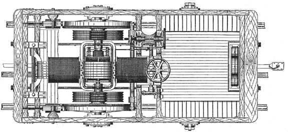
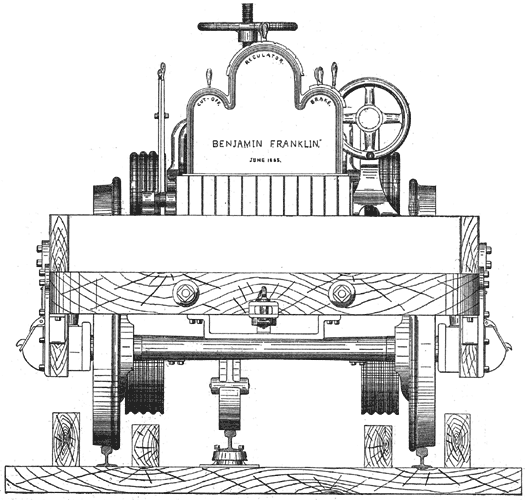
Our illustrations show the arrangements of the motor in detail, as it stands on the track, the cab being removed for the sake of clearness.
 |
| Fig. 2. — Plan of Motor "Benjamin Franklin." |
In the arrangement of his motor Mr. Daft has entirely avoided the use of belts, power being transmitted by friction from the armature to the drivers, and the amount of it can be regulated at will according to the load. As will be seen from the plan, Fig. 2, the motor-dynamo is supported at the rear on a shaft resting in bearings; its front end is supported by a threaded eye through which passes a long screw, which is turned by a hand wheel, as shown in the side-elevation, Fig. 1. The armature shaft carries a friction wheel 9 inches in diameter, which bears upon a larger friction wheel 3 feet in diameter, keyed to the axle of the main drivers. With this arrangement it is obvious that by turning the large screw the upper friction wheel can be pressed against the lower to any desired degree, thus preventing slip, even with the heaviest loads. By means of the screw also the entire motor-dynamo can be raised clear above the driving wheels, so that the armature can be taken out and inspected with convenience.
 |
| Fig. 3. — "Insulator." |
The bronze contact-wheel which bears against the central rail is 15 inches in diameter and is raised and locked by the two levers at the near side in the view Fig. 1. Another lever on the other side constitutes the "reversing-lever," by which the brushes of the dynamo are set so as to give the motor a forward or backward motion. There are two pairs of these brushes and the motion of the lever alternately puts either pair in contact with the commutator. Like all of Mr. Daft's railway motors, this one is provided with his electric brakes. These consist of large electro-magnets which, being energized, are attracted by the wheels and press against them like the ordinary brake. The motor-man occupies the clear space in front of the motor-dynamo, and before him is placed the case containing the regulating, brake and cut-off switches, as shown in the end view, Fig. 4. The switch at the right controls the brakes and that to the left makes or breaks the current as desired. In the centre is placed the "regulator," by which the speed of the motor can be altered at will. There the terminals of the compound winding of the motor-dynamo are brought, and by bringing the lever to the different notches the resistance of the field-magnet coils is altered, which changes the speed correspondingly. The driving wheels are 48 inches in. diameter, the trailing wheels being 36 inches. Their shafts supporting the motor-dynamo rest in specially designed resilient bearings, so as to reduce the shock to a minimum.
 |
| Fig. 4. — End View of Motor "Benjamin Franklin." |
The motor is designed for 75 horse-power, and a normal speed of 18 miles per hour, with a possible speed of 40 miles. The motor complete weighs nine tons, and measures 14 feet 6 inches in length, over all.
