[Trade Journal]
Publication: Electrical World
New York, NY, United States
vol. 7, no. 6, p. 55-56, col. 2-3,1
The Bain Electric Lighting System.
The system of arc and incandescent lighting illustrated and described on this page is the invention of Mr. Forée Bain, of Chicago, and is one in many respects worthy of special notice.
 |
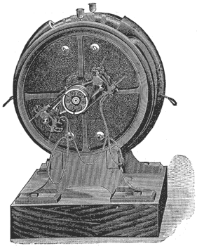
| Fig. 1. — the Bain Dynamo. |
The generator, as the most cursory glance at Figs. 1, 2 and 3 will indicate, possesses novel features of a mechanical and electrical nature. The inventor's object has been to couple the coils on the armature so as to realize the full effect of their producing power, and to reduce the internal resistance at the same time. It is well known, says Mr. Bain, that batteries differing in electromotive force will not work economically in the same circuit, as those of a higher E. M. F., are found in practice to be reduced in efficiency by those of a lower E. M. F., the work performed in the latter raising them to an equal potential, notwithstanding the theory to the contrary. The resultant current is found to approach the mean instead of the sum of the electromotive forces. If for chemical batteries, argues Mr. Bain, be substituted coils on an armature (as in the Gramme type), and those coils so connected be passed through magnetic fields, the lines of force varying from zero to the maximum, it will appear that the E. M. F. of each individual coil will be in proportion to the number of lines of force under which it passes, or the E. M. F. is in proportion to the density of the magnetism nearest such coil, supposing, of course, the speed to be the same for each coil. Hence we would have currents produced from each coil decreasing directly as the magnetism decreases. Now as these coils are connected in series, the current from the coils generating the higher E. M. F. must pass through those of a lower E. M. F., with the defect as before stated.
 |
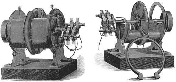
| Figs. 2 and 3. — Side Views of Bain Dynamo. |
The connections and commutations of the circuits are such in the Bain dynamo that the current from the coils in fields of higher strength which are in series is split and passed through fields of lower strength in parallel, by which means the internal resistance is greatly reduced and the fall of potential in the coils of higher strength is so slight as to hardly affect their efficiency. When coils are generating currents of equal E. M. F. they are in series; and when a pair of coils approach and are about to pass the neutral line, and for a short time after passing the neutral line, they are disconnected from the main circuit and connected together so as to oppose each other. By this means the discharge of the coils at the commutators and brushes is prevented, and sparking is suppressed, and the coils are not included in the main circuit when not contributing to it.
The armature is of the disc form. It is built of uniform width (2 inches) in all sizes, but varies in diameter. The larger dynamos have two and three armatures connected in series, but these have only one commutator. The armature runs without noise, the spaces between the coils being filled in with wooden blocks held on by having portions of the coil wound around them. In constructing the armature, a spider having six arms and turned flat at the peripheries of the arm is mounted on a special lathe, with two discs, one on each side of the spider. The discs are the size in diameter of the core to be wound. Wrought iron ribbon one inch wide and one twentieth thick is wound on the spider very tightly, and a strip of paper is wound on at the same time, parallel with the iron ribbon. By this means each and every convolution of iron ribbon is insulated from its neighbor. When the desired diameter is reached, three layers of iron wire are tightly drawn and wound over the whole. This wire is put on hot, and on beginning to cool is soldered into a solid band. It is thus held as firmly and strongly on the spider as if it were one piece. It will be seen that there are no nuts, bolts, screws or wedges used in the construction. Six coils of wire, seven layers deep in every case, are now wound on the armature core. Between the coils are placed wedge-shaped blocks half an inch thick, coming out flush with the coils. The blocks have grooves cut into them deep enough for one layer of wire and about five-eighths of an inch wide, into which are wound part of the coil on each side. The object of the blocks, as above intimated, is to make an even cross section of the armature, in order that it shall not beat the air with the coils.
After the coils are wound on, they are connected in pairs, opposite coils constituting a pair; but they differ essentially from all other dynamos in that both unlike ends of the coils are connected together into loops, and these loops are tapped on each side by wires which are carried to the sections on the commutator. By this means the coils are never on open circuit, even when disconnected from the main circuit.
 |
| Fig. 4. — Bain Arc Lamp. |
The field of the Bain dynamo is made entirely of cast iron, and consists chiefly of two pieces exactly alike held together by two rings which are also secured to the feet by means of one bolt through each ring, there being a ring at, each end. These are the only bolts in the whole machine, which they serve to hold together while securing it to the base, as seen in Fig. 8. In manufacturing these dynamos, the entire "scale" is removed from the iron, as the scale acts as a magnetic shield and necessitates the expenditure of a greater quantity of current for the saturation of a given piece of iron. When the castings come from the foundry, the edges where the large pieces join at the yoke are planed off. They are then clamped together and "chucked" in the lathe. The bearing supports are bored out, after which the work is mounted on a boring bar which also serves for a mandrel, and the entire casting is turned up from a common centre. The pole pieces are bored out by an automatic boring bar on which if is now mounted, and when it comes from the lathe it goes to the planer. It is finished in the lathe with a single chucking. The planer work does not occupy a very long time. The rings and feet are bolted together and bored out so as to clamp over the ends of the two castings, and the entire field is ready to be japanned. The castings are japanned all over, to prevent rusting and sweating under the coils. In this manner the field is completed entirely by machinery. The joint where the two field pieces are brought together is thoroughly covered by the large rings at each end, the superficial contact of the rings being so great that the yokes of the magnets at the joint are perfectly neutral, there being no "consequent point" and loss of magnetism.
When it is desired to take the armature out, the only thing necessary is to remove the two bolts, turn the field one-quarter around, remove the rings and lift off one-half of the field. Fig. 3 shows the machine in this condition. The pieces cannot be put back incorrectly. The bearing supports are cast integral with the field being, in fact, part of it. Boxes fit into the same, which act also as dowels, to prevent any lateral displacement of the parts. The bearings are firm and rigid; the boxes are easily renewed when necessity requires it. The field is turned out so as to be nearly three-quarters of an inch larger in extreme diameter than the armature, to allow for expansion as well as any slight displacement that might occur due to centrifugal motion.
In this construction of the field magnets, it would appear that the lines of force are directly concentrated on the armature, and are not deflected by the superfluous iron of other portions of the dynamo. The field pieces are duplicates in every respect, and hence the magnetic density of the poles is exactly equal, a point sometimes overlooked by dynamo builders. The cores of the field magnets are very heavy, but the pole pieces are usually thin, not over half an inch in any case, the object being to saturate the iron evenly without creating a reaction by the development of an opposite internal pole, as would be the case were the iron too heavy or too thick to be thoroughly saturated.
The wires from the armature to the commutator are carried through grooves cut into the shaft, over which is secured a thimble which constitutes the bearing at the commutator end. The commutator is easily accessible. Any of the sections may be removed from the commutator without disturbing the connections, and can be easily and quickly replaced without fear of mistake.
 |
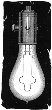
| Fig. 5. — Bain Incandescent Lamp. |
The arc lamp, Fig. 4, of the Bain system is of the clutch type, and, except in a few mechanical details, does not materially differ from others in the same category. The incandescent lamp, Fig. 5, has not yet been put on the market. Its novelty consists in the manner of connecting the filament with the leading-in wires, and in the material of which the filament is composed, Mr. Bain has not patented either the manner of connection or the process of manufacture, preferring to keep them secret. The holder is made almost entirely of wood, and while presenting a handsome appearance, has the essential quality of cheapness.
The Bain system was employed to light the last Chicago Exposition, using 150 arc lights, and the illumination was very satisfactory to all concerned. There was not a single extinction due to failure of electrical apparatus, Patents; broadly covering the method of connecting the armature have been secured all over the civilized world, and in addition about twenty patents have been issued in the United States covering details of manufacturer and construction. The inventor of all is Mr. Forée Bain. The reason why so little has lately been heard of this system is the death of Capt. A. E. Goodrich, who owned the factory and system in about equal shares with Mr. Bain. Since Capt. Goodrich's death the factory has stood idle, and his whole interest is now for sale. It appears not at all unlikely that it will soon find a purchaser and the system be again brought prominently before the public. The factory, it may be mentioned, is a five story and basement brick building, 50 X 100 feet, corner of Franklin and Illinois streets, Chicago, fitted throughout with machinery, some of which has been specially designed for the manufacture of the system. Its capacity is a 40-arc light plant, complete, every working day.
