[Trade Journal]
Publication: American Electrician
New York, NY, United States
vol. 12, no. 1, p. 20-23, col. 1-3,1
Aluminum Feeders on the Northwestern
Elevated Railroad, Chicago.
One of the foremost intramural transportation systems of the country, the new Northwestern Elevated Railroad of Chicago, has adopted aluminum feeders for its extensive electric system. Over 24 miles of single track are being equipped for heavy traffic by means of electrical motors, 150,000 pounds of the new rival of copper having been purchased tor the purpose. As something over one-half of this large amount of aluminum has already been put in place, it is now possible to observe on the installation the methods used in handling the wire and the manner in which some of the more evident difficulties in its use are overcome.
The Northwestern Elevated Railroad is the last to approach completion of the great transportation projects fathered by Mr. Charles T. Yerkes. In many respects this latest child of Mr. Yerkes is the most remarkable. From the time the first drawing was made, the order has been in force to make the new road the most perfect piece of transportation property that money can buy. Consequently both in design and execution, every part and appurtenance of the great structure represents the latest and most advanced ideas in rapid intramural transit. It is under this extremely favorable condition that the experiment of using aluminum feeders is being tried.
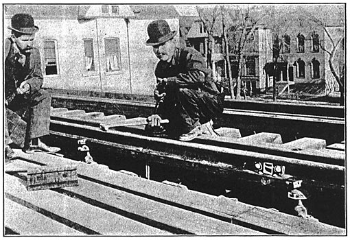
| |||
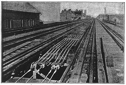
| The Terminals of the Aluminum Feeders. The Ends of the Feeders Are Soldered Into Copper Connectors With Depending Lugs to Which Copper Feeders, Rising From the Ground Below, Will Be Soldered. the Connectors Are Bolted to Cross Bars to Which Are Also Fastened Steel Cables Through Strain Insulators. |
Briefly, the Northwestern Elevated Railroad consists of 5 1/2 miles of four-track elevated structure and one mile of double-track structure. The double-track structure extends from the junction with the union elevated loop in the heart of the main business district of Chicago, along Wells and Franklin Streets to Chicago Avenue. From that point to the terminal at Wilson and Evanston Avenues, the four-track structure stands on its own right of way, secured by purchase. The general direction is northwesterly from the business district. The terminus at Wilson Avenue is close beside the tracks of the Chicago, Milwaukee and St. Paul Railroad's Evanston branch, and the Evanston Avenue trolley line of the Chicago Consolidated Traction Company. The Milwaukee and St. Paul road is now trying to secure permission to change the motive power on the Evanston branch to electricity, in which event its cars will probably use the Northwestern elevated's structure into the center of the city. As the northern portion of this steam line's tracks are now being used by the Chicago and Milwaukee Electric Railway, a complete electric service from the heart of Chicago to Milwaukee seems eventually assured.
Throughout the four-track structures of the Northwestern Elevated Railroad an express and local service will be maintained. The express service will be fast, with stops a mile apart. The local service will be slower, with stations every 1500 feet. At the express stops the transfer from one set of trains to the other will be made by merely walking across a platform. The two-track structure and its two stations will be used alike by both sets of trains.
The well-known third-rail system has been installed throughout the Northwestern elevated railroad. Equipment consisting of heavy motor cars and lighter trail cars will be employed, of a general appearance closely resembling the equipment in use on the Metropolitan and Lake Street elevated roads in Chicago. The power house for the line is located at Southport and Fullerton Avenues, between 3000 and 4000 feet from the structure.
| |||
| A View of the Curve Construction Showing the Use of Split-Spool Insulators and Vitrified Clay Supports. |
As may be well guessed, the reason why aluminum was decided on for the feeder system of the Northwestern Elevated Railroad over copper was its greater cheapness, with equal degree of efficiency. Electrical Engineer J. R. Chapman reasoned that for the purposes of the road aluminum was equal to, if not superior to copper, and was considerably cheaper. Hence its use. In March, 1899, when the question came up, Mr. Chapman figured that 48 pounds of aluminum of the conductivity offered to the road was equal in current-carrying power to 100 pounds of copper of the ordinary 98 per cent. conductivity. As copper at that time was quoted in the market at 18 cents a pound, he figured that he could afford to give 36 1/2 cents a pound for aluminum. But aluminum was selling then close to 30 cents a pound, so Mr. Chapman decided to use it. He made a deal a little better than the figure given, and saved his company something over $8,000 by the substitution of the white metal.
The aluminum bought for the Northwestern Elevated Railroad is entirely for the feeder system, and is confined to the portion running along the structure. From the power house to the structure the current is transmitted by lead-covered copper cables, which run along Dunning Street in vitrified clay conduits. Over 10,000,000 c. m. in copper cables are carried in the conduit. The 40 ducts of the conduits also carry 8 1,000,000-c. m. tinned bare copper return cables, which connect the structure with the negative side of the switchboard. At the junction of Dunning Street and the Northwestern elevated line six manholes are located, out of each of which six three-inch wrought-iron pipes run up pillars of the structure. The 36 pipes carry the lead-covered copper up to its point of junction with the aluminum, and also bring back the return cables attached to the iron work of the structure. In this connection it may be noted that the entire structure is used as a return, each rail of the track being bonded to the iron work with a flexible bond, no bonds being used at joints except in the case of the trolley rails.
| |||
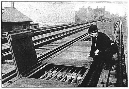
| A. Section of the Finished Feeder Box Showing Two of the Trap Doors Over the Insulating Supports Open. |
The aluminum feeders run from the point of junction with the underground system to the taps for the trolley rails on all parts of the structure. They consist of bare stranded cables of three sizes, 1,365,000 c. m., 1,050,000 c. m. and 785,000 c. m., though there is but little of the last size used. The largest size is, roughly speaking, about 1 1/2 inches in diameter. It is "cable laid," consisting of 49 separate strands, and is astonishingly strong for its weight. The wire is handled in large spools of the size used for large copper cables. The spools, however, instead of weighing 3800 to 4600 pounds, as in the case of copper, only weigh about 1600 pounds. The advantages in ease and cheapness of handling are evident.
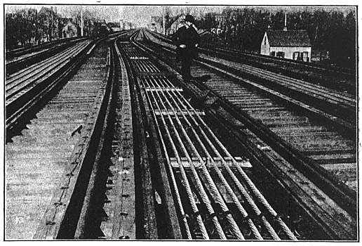
These bare aluminum cables are laid in a feeder box built of pine, along the center of the structure. There are in all about 24,000 feet of the boxing, of varying width, according to the number of cables carried. The largest number of cables in the boxing is eight, and the smallest two. The track is divided into five sections, each getting its quota of cables. Besides the aluminum feeders the boxing also carries a 30-pair telephone cable for communication with the stations, and a 350,000-c. m. insulated copper cable for lighting purposes.
 |
| A Full Size Cross Section of the 1,050,000-C. M. Cable. |
%%The aluminum cables are laid in the feeder box on vitrified clay insulators placed on cross ties every 9 feet. Every twentieth set of supports consists of Anderson split-spool insulators, which are clamped tight to the wire, and give the needed strain.%% On the curves the vitrified clay supports and the iron chairs alternate. After the wires are put in place in the boxing the latter is covered over and forms a footway in the center of the structure. Loose covers or lids are left at each insulator for access in case of repairs or changes. It is evident that this method places practically no reliance on the tensile strength of the aluminum cables, since they are supported every 9 feet and anchored every 180 feet. Questions of insulation tor the cables are also avoided.
The ends of the aluminum cables are anchored in a singular and highly effective manner. To the cable are soldered large copper connectors, which, in turn, are attached to Brooklyn strain insulators made for the purpose. These latter are held by heavy bare iron wires attached to eye bolts in wooden cross pieces. The copper connectors have another opening for copper wire of a carrying capacity equal to the aluminum. This arrangement is used where the underground wires connect with the aluminum feeders on the structure, and also at all special work and points where the path of the feeder boxing is interrupted. In such cases as the latter the ends of the aluminum cables are anchored, and insulated copper wire is run down under the tracks and past the obstruction, being connected with the ends of the aluminum cables again beyond.
| |||
| One of the Third Rails Showing the Copper Taps Running to the Aluminum Feeders in the Main Boxing and Showing Also A Bond and the Insulating Chairs. |
This scheme for anchoring the ends of the cables also exemplifies how the cables are spliced. For the successful carrying out of all splicing operations, which have always been considered one of the most difficult points in the electrical use of aluminum, a remarkably simple method has been adopted. A plain copper connector of the ordinary type receives the two ends of the wire, which are then soldered fast into the connector. The only difficult point is the question of solder. This has been successfully solved by a machinist who works for the Northwestern Elevated Railroad, H. L. Gronimus by name. After considerable experimentation he has found a composition of metals which will not only successfully solder aluminum to copper, but also aluminum to aluminum. Naturally he declines to state the materials in his solder, but its results on the Northwestern Elevated show the value of the composition.
Connectors are also used in making taps from the aluminum feeder cables to the trolley rail. This trolley rail is raised up on double petticoated insulators above a wooden string piece, the joints being well bonded by flexible bonds. Taps run from the feeder cables to it every 1500 to 2000 feet. Either one or two strands of 0000 insulated copper cables are used for the taps, except at the ends of the feeders, where a tap of practically the same carrying capacity as the cable is used. These taps are soldered to copper clamps which are tinned and then screwed tight around the feeder cables. The clamps are not soldered to the aluminum, pressure alone being relied on for a good contact. The junctions with the cables are covered with tar or pitch paint. At the other end the taps are soldered to copper plates, which are riveted to the trolley rails.
Of the general character of the electrical work on the Northwestern Elevated Railroad no better idea can be given than that obtained from the statement of E. J. Ward, the superintendent in charge of the electrical construction, who states:
"The electrical work on the Northwestern Elevated Railroad is far superior to any I have ever seen. Our orders have been to neglect no opportunity to improve on the methods and material used on the other roads. The result has been to produce what I have no doubt is the best piece of electrical elevated railroad construction of the world."
Under these auspices the trial of aluminum conductors on the Northwestern Elevated Railroad ought to give most valuable results. Mr. Chapman is keenly interested in the experiment if experiment it can be called and expects to prove much to the credit or disadvantage of the new substitute for copper. Among other things he intends putting a piece of bare aluminum cable in circuit with one of the return copper cables and locating the piece in the worst man hole in his underground system. From this he expects interesting comparisons with copper in another field.
