[Trade Journal]
Publication: American Electrician
New York, NY, United States
vol. 12, no. 3, p. 107-112, col. 1-3,1
THE NEW WATER POWER OF THE HARTFORD ELECTRIC LIGHT
COMPANY.
BY PROF. W. L. ROBB.
During the past year the Hartford Electric Light Company has added to its water power by developing a second power on the Farmington River. This power is situated eleven miles from the central station in Hartford; approximately the same distance from Hartford as the power previously developed, but three miles further up the river.
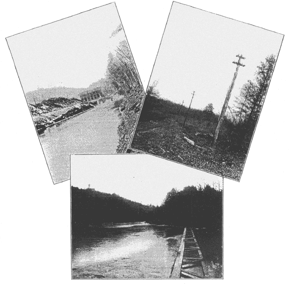 |
| (Left) Fig. 1. the Tail-Race Formed by Deepening A Branch Channel of the River Around the Island. (Center) Fig. 3. the Boom Above the Dam Keeping Ice and Driftwood From the Feeder Tubes. (Right) Fig. 2. A View of the Pole Line Showing the Arrangement of Cross-Arms and Wires. |
The location for the new dam is ideal. The banks and bed of the river at this point are of trap rock, practically free from seams; the river is vary narrow and the banks are almost vertical The fall in the river which could be obtained at this point is 25 ft. About two hundred feet below the site of the dam the river is divided into two channels by an island about one thousand feet long. The fall in the river to and alongside this island is about six feet. There is no satisfactory site for a dam at the lower end of the island, as the river at this point is comparatively wide, the banks are low, and the bed of the river would not furnish satisfactory foundation. As it was desirable to obtain the six additional feet of fall the inlet into the narrow channel was closed and the channel deepened to make a satisfactory tail-race, and thus to make it possible to use the six feet additional fall. The power house was located at the head of the tail race, about two hundred feet below the dam, it being found preferable to improve the channel above mentioned for a tail race rather than to extend the feeder pipes and locate the power-house further down stream.
| |||
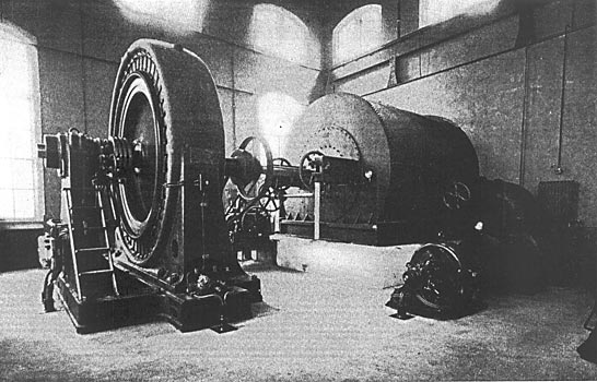
| Fig. 4. One Complete Set of Wheels, Generator and Exciter. |
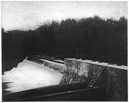
The dam was built of concrete, as there was no stone to be obtained in the immediate neighborhood for the construction of a stone dam. The trap rock taken from the wheelpit and from the upper end of the tail race proved just sufficient for the stone in the concrete. There was the further advantage in favor of the concrete dam that it could be constructed in very much shorter time than could a stone one. All the work, including dam, power house, machinery and transmission line, was completed within seven months after letting of contract. Sections of the dam are shown above in Fig. 6. The crest of the dam is about 180 ft. long, while the waste-gate abutment, forebay and end abutment are about 80 ft. long. The thickness of the dam at the base is about 32 ft., and at the crest 6 ft. The height of dam is about 25 ft. above surface of water.
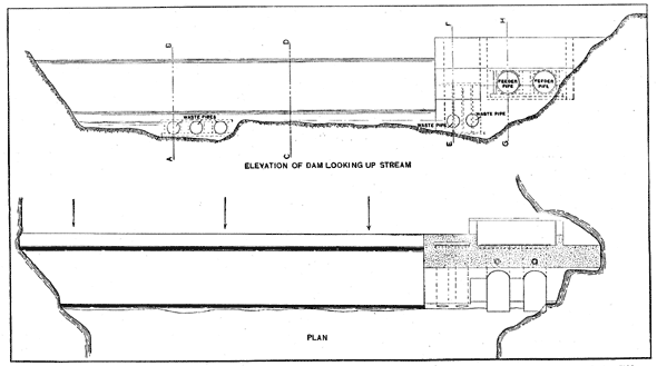 |
| Fig. 5. Plan and Elevation of Dam, Showing Location of Temporary Waste Pipes for Carrying Flow of River During Construction. |
In preparing the foundation for the dam the water in the river was diverted by cofferdam and crib, and the water was pumped out until rock was exposed. Loose gravel and rock were removed, and the old surface of the rock was taken off by squib blasts, so that the cement concrete could have a clean, sharp surface to which to adhere. All the surfaces of the rock were made to slope upstream. At the ends of the dam and abutment loose rock was removed and squib blasts were put in to remove the old surface.
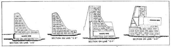 |
| Fig. 6. Sections of Dam on Lines Shown in Fig. 5. |
The section on line, A B, shows the contour through the deepest part of the river. The cofferdam was built around this portion, and three waste pipes 5 ft. in diameter were built in this portion of the dam as shown in the sectional drawing. These three waste pipes were capable of carrying the normal flow of the river during the further construction of the dam. On the upstream end of these waste pipes a timber frame was built in the dam, and when the dam was completed and ready to be filled they were permanently sealed with 12-in. by 12-in. Southern pine timber.
| |||
| Fig. 7. View of Dam From Forebay End. |
The section on line E F indicates the construction through the waste-gate abutment, and shows two waste pipes 5 ft. in diameter. These waste pipes are controlled by gates, and were built in the dam so that the electric light company could control the level of the water on the dam, except in flood time. It was considered advisable to do this so that the electric light company could build the dam to the extreme height of the flowage rights which it controlled. In case the load is light the waste gates can be opened to prevent the water setting back on the next water power. Section on line G H is taken through a feeder pipe. The feeder pipes are 9 1/2 ft. in diameter and about 200 ft. long.
| |||
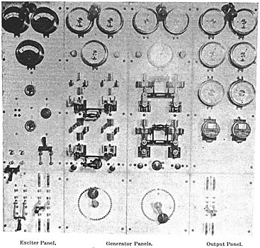
| Fig. 8. A View of the Switchboard. |
The dam, forebay and abutments are built of concrete. First, a bed of concrete, 12 ins. deep was made; then blocks of stone were placed in the soft concrete with the smallest surface down. These stones were not allowed to come within 12 ins. of each other. Concrete tor the body of the dam and abutments, where random block stone was allowed to be used, was composed of one part Portland cement, having a tensile strength of 500 pounds to the square inch, of three parts clean, sharp sand, and three parts broken stone that screened 2 ins. The block stone used was taken from the trap-rock excavation for the wheelpit and consequently had clean sharp surfaces. Twelve inches of the outside of the dam and all the outside surface were built of concrete composed of one part Portland cement, three parts of clean sharp sand and two parts of broken stone that screened 1/2 in. The completed dam and abutments and a portion of two of the feeder tubes are shown in Fig. 7. The view of the river above the dam, showing the boom for keeping the ice and driftwood away from the feeder tubes is shown in Fig. 3. This boom is constructed in the form of a truss out of 12-in. by 12-in. timber, braced with 3-in. planking. The tail race, which was constructed by deepening the narrow channel of the river about 4 ft., is shown in Fig. 6.
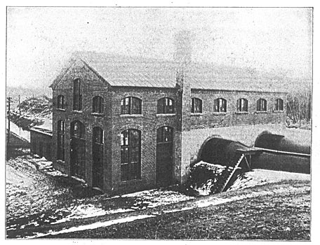
The power house is 42 ft. wide by 84 ft. long, and 29 ft. from the floor to the lowest chord of the roof trusses. The bottom of the tail race under the power station is excavated 24 ft. below the floor, and the water in the tail race stands 15 ft. below the floor of the station.
| |||
| Fig. 9. Joint in Aluminum Wire. |
The floor of the station and the machinery, including generators and wheels, are carried on concrete arches built in the tail race. The concrete used in these arches is composed of one part Portland cement, three parts of sand and four parts of broken stone which screened 2 ins. The exterior of the power house, with lightning arrester and oil-house, are shown in Fig. 10.
EQUIPMENT OF POWER HOUSE.
Power is developed by means of two pairs of horizontal turbine wheels, each pair capable of delivering to generator coupling 1150 h.p. at 164 r.p.m., with 29 ft working head. These wheels were manufactured by the Stilwell-Bierce & Smith-Valle Co. Each pair of wheels is set in a flume 12 ft. in diameter and 23 ft. long, made of 5/16-in. steel, and discharges into a center cast-iron case, with a draft tube flaring from 8 1/2 to 11 1/2 ft. in diameter, 23 ft. long and made of 1/8-in. steel. The wheel shafts are made of the best forged steel 7 3/8 ins. in diameter, and direct-connected by standard face coupling to the shaft of generators. There are two wheels tor exciters, each set in a cast-iron case, and capable of delivering to each. exciter 45 h.p. at 550 r.p.m., under 29 ft. working head. The draft tube of each exciter wheel is connected to the draft tube of the generator wheel, and the exciter feeders are tapped out of the sides of the flumes of the main wheels. Each pair of generator wheels is direct-connected to a 750-k-w. generator, and each exciter wheel is connected to a 30-kw. generator. Fig. 4 shows one of the two generating sets complete with exciter set.
| |||
| Fig. 10. View of Power House From Up-Stream Side. |
The station is equipped with a motor-driven air compressor having a capacity for compressing 5 cu. ft. of tree air per minute against 150 lbs. pressure to the square inch. The compressor is connected with the necessary piping and valves to the generators and switchboard, and the air thus compressed is used for cleaning the apparatus.
The station is equipped with a 15-ton traveling crane, and the water-wheel casings are brought into the power house so that the crane can be used in handling all machinery.
The generators were manufactured by the Westinghouse Electric & Manufacturing Company, and generate two-phase alternating current under a pressure of 500 volts. The current passes to raising transformers and is changed over to a three-phase current under a pressure of 12,000 volts, at which it is transmitted to the central station at Hartford. At Hartford the pressure is lowered to 2400 volts, and feeds into the busbars in parallel with the current from the other water power station, and the local steam station. Electrically, the two water power stations are situated 22 miles apart.
A diagram of the connections of switchboard is shown in Fig. 11, and Fig. 8 is an illustration of the switchboard at the power station. The switchboard consists of four panels. The first contains ammeters and voltmeter for the exciters, the second the necessary switches tor both phases of one of the generators. The third panel is similar to the second. The fourth panel is a load panel, and contains ammeter, voltmeter, Indicating wattmeter and recording wattmeter tor each phase.
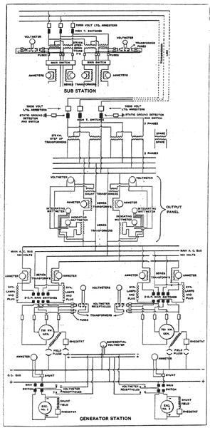 |
| Fig. 11. Diagram of Circuits of Generating and Sub-Stations. |
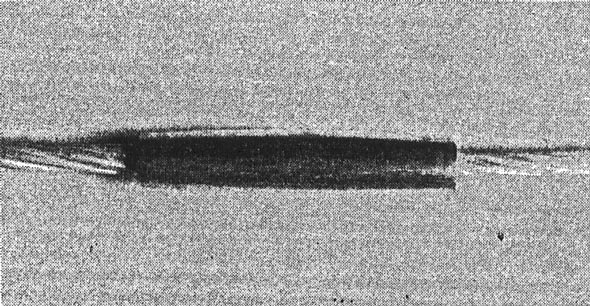
One of the most interesting features of this particular transmission is the line. The current is transmitted from Farmington to Hartford over aluminum wire, this being the first case in the East where this wire has been used. The wire used is equivalent in conductivity to No. 0000 copper. The line was built of aluminum primarily because it could be purchased at 20 per cent. less than copper having the same conductivity. The wire used is made of seven strands. Until the wire reaches the underground district in Hartford, it passes along a private right-of-way; the first half mile over property of the electric light company, and the remaining distance along the tracks of the Central New England Railroad. The wire used is not insulated, the insulation relied on being the porcelain insulators on which the line is supported. The porcelain insulators are double petticoated and are about 6 ins. in diameter at the base. The wire was furnished in lengths of about 2000 ft. The joints were made in the following manner: the ends of the wire were first cleaned with hydro-fluoric acid, and then tinned over. The strands of the wire were somewhat spread apart and placed end to end in a brass casting, the inside of which was somewhat oval. The casting was then filled with block tin. A test of several of these joints was made in a testing machine, and their tensile strength proved to be greater than that of the line itself. Figs. 2 and 9 show the general construction of the line, and one of the joints in the aluminum wire.
The total cost of this development. Inclusive of water rights and transmission line, was $125 per horse power. The specifications and drawings for the dam and hydraulic machinery were furnished by Mr. A. C. Rice, of Worcester, Mass., who acted as consulting hydraulic engineer to this work.
*Consulting Electrical Engineer of the Hartford Electric Light Company and Resident Engineer in Charge of the work described herein.
