[Trade Journal]
Publication: Electrical Industries
Chicago, IL, United States
vol. 5, no. 5, p. 142-144, col. 1-2,1
Electric Power in Taftville Cotton Mill.
The advantages of electricity for power transmission is shown by the number of recent installations and especially in utilizing water powers at some distance from the factory. At Taftville, Conn., are located some important cotton mills using the power of the Shetugket river. In the mills of Mr. E. P. Taft at Baltic and Taftville, the valuable water rights of the river have been developed, and by an electric plant the power is distributed to the mills, replacing two 350-horse power engines.
| |||
| Fig. 1 Electric Power in Taftville Cotton Mill. |
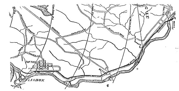
In Fig. 1 are shown the relative positions of the generating station at Baltic and the receiving station at Taftville. The line is nearly four and one-half miles in length and is carried along the highway up the river, skirting its banks in places and crossing it at intervals to shorten its route. In the basement of this building are the wheel and dynamo rooms of the generating plant. Four hundred feet above the mill a dam 525 feet long has been thrown across the river. The effective head on the turbines is 32 feet and the water available, even in the driest seasons, is sufficient to furnish not less than 1,500-horse power. The turbines are belted to pulleys on the main line shaft, extending the whole length of the wheel room and continuing through the partition walls into and along one side of the generator room. The pulleys are thrown into, or out of, action by Hunter clutches mounted with pulleys on quills, so that any or all of the wheels can be applied to driving the shafts. Similar pulleys and clutches are furnished in the dynamo rooms for throwing in or out the various machines that may there be placed.
| |||
| Fig. 2 Electric Power in Taftville Cotton Mill. |
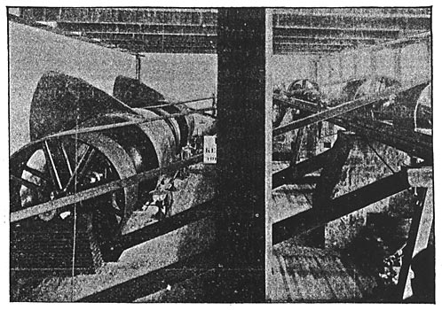
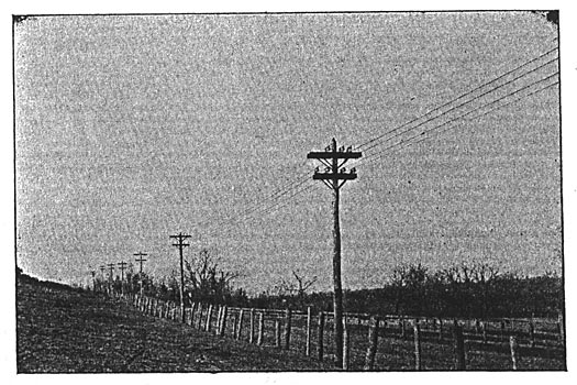
Fig. 2 shows the wheel room and the arrangement of the turbines and line shaft. There are three double 42-inch horizontal wheels and one double 27-inch wheel, the former developing 800 effective horse power, at 157 revolutions per minute, and the latter 300 horse power at 244 revolutions per minute. The belts pass obliquely upward to the pulleys on the line shaft, and the turbines are kept at speed by Schenck electric governors, which have proved themselves capable of doing very fair service. The wheel plant and shafting were made and installed by the P. C. Home Company, of Gardiner, Maine. The line shafting is supported by heavy iron girders set on stone piers and additionally braced by timbers. The dynamo room, beside the shafting, is occupied by two 250 K. W. General Electric three phase generators, delivering current to the line at 2,500 volts. Each machine is provided with its own exciter, a 3 K. W. bipolar dynamo. The three-phase machines run at 600 revolutions per minute, and are set so firmly on substantial foundations as to run with scarcely a perceptible vibration. The driving pulleys on the main shaft are fitted with Hunter clutches, so that either machine can be dropped out without the slightest disturbance to the service. The line, a characteristic bit of which is shown in Fig. 4, is a good piece of construction work on substantial wooden poles placed 100 feet apart. The upper wires on the cross arms are of No. 0 bare copper and form the original three-phase circuit designed for the transmission. The wires on the lower cross arm are No. 0000 insulated wire, and are four in number. They were originally intended for a railway circuit, the generators for which were to be installed at Baltic to feed the Norwich Street Railway; but as the amount of copper necessary to do the work successfully appeared too great, the system was changed, a second three-phase generator and motor were added, and three of the four proposed feeder wires were utilized for the three-phase circuit. All are supported on the General Electric Company's standard insulator, the fourth No. 0000 wire forming a convenient relay in case of accident to any of the others.
| |||
| Fig. 3 Electric Power in Taftville Cotton Mill. |
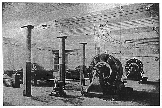
At Taftville the three-phase circuits are led into the basement of the new mill, where they drive two three-phase synchronous self-starting motors, identical in size with the generators at Baltic. These machines replace the two Corliss engines previously used. These motors are belted to the jack shafting previously driven by the engine, the pulleys on the shaft being equipped with friction clutches so that the load can be thrown from engine to motor, or back again, without any interruption of service. The motors start entirely unaided, coming up to synchronous speed in about fifty seconds from the time the current is thrown on. They are, like the generators, separately excited, the exciters being driven from the pulleys on the end of the motor shaft.
| |||
| Fig. 4 Electric Power in Taftville Cotton Mill. |
The efficiency of the complete transmission at full load, from the power applied to the dynamo pulley to that delivered to the motor pulley, is 80 per cent. In originally starting the mill before the second motor was ready for operation, it was the custom to bring the motor up to speed, and then gradually throw in the clutch connecting it to the shafting already running from one of the engines. When the clutch was fully in and engine and motor running together, the engine was disconnected by its clutch and the power transferred entirely to the motor. This could be done without producing the slightest disturbance in the speed, and in the same way, now that both motors are in and the engines shut down, the load can be shifted from one motor to the other if desirable. Ordinarily, however, there is work enough for both, when driving the 1,700 looms in the new mill, operating the lighting plant and the three 80-horse power General Electric railway generators, installed in another part of the basement.
| |||
| Fig. 5 Electric Power in Taftville Cotton Mill. |
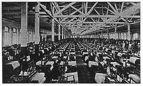
Fig. 5 shows the upper weave room of the new mill driven by these motors, and gives some idea of the work done by the motors and the extensive operations of the
