[Trade Journal]
Publication: American Electrician
New York, NY, United States
vol. 17, no. 7, p. 349, col. 2
Abstracts from Foreign Contempories
·
·
Lightning Arresters Alberto Dina contributes to a late number of Elektrotechnische Zeitschrift an illustrated article on various designs of lightning arresters with particular reference to the relay built by the Siemens-Schuckert Works. The most suitable length of air gap for relative low voltages of a few thousand volts is said to be three to four millimetres. All attempts to lengthen the air-gap by giving special forms to the electrodes, as for instance by giving them sharp edges, have proved unsuccessful, since after numerous discharges have taken place the sharp edges are destroyed. Artificial air-gaps have been introduced in many instances for the purpose of starting the discharge. Either the heat effect or the ionizing effect of the ultra-violet light of the stroke starts the discharge through the main air-gap. Fig. 8 shows such an arrangement in which Be is the auxiliary air-gap, and BA the main air-gap. A modification of this arrangement is shown by Fig. 9, in which three discharges may take place; first between ee, then between B and e and finally the main discharge from B to A. Further modifications of this scheme are, of course,
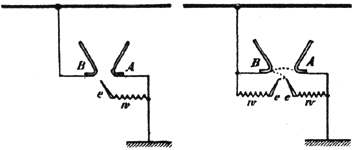 |
| Fig. 8. Lightning Arresters.Fig. 9. |
possible by using successive auxiliary gaps like that at ee, one below the other and with decreasing lengths of the gap so that the lowest and shortest gap is first acted on. This starts the discharge through the next one above and so on. The disadvantage of this arrangement is that the auxiliary air-gap must have a short length and is liable to be changed in time, and the wind may, moreover, blow the discharge from the main gap to the auxiliary gap, and it may remain where there are ho special devices provided for extinguishing the arc quickly. The Siemens-Schuckert lightning arrester is shown by Fig. 11. The device makes use of a special circuit in which high frequency oscillations are produced. W is the damping resistance and B A is the main air-gap. C C1 are condensers, F is an auxiliary air gap, P
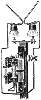 |
| Fig. 10. Lightning Arrester. |
the primary and S the secondary of a transformer. When the voltage at the plates of the condenser C (which is practically equal to the voltage between line and earth) reaches the value to which the air-gap F is adjusted, the condenser C discharges partly through the circuit C F C1 P, i. e., it transfers a part of its charge to the other condenser C1, high frequency currents being produced. This discharge depends in no way on the methods by which the condenser C has been charged (that is, on the causes of the excessive rise of voltage in the line). The oscillating currents in the primary P
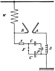 |
| Fig. 11. Siemens-Schuckert Lightning Arrester. |
produce a high e.m.f. in the secondary S of of the transformer, so that now a higher voltage exists between B and A and the discharge from B to A is started. This higher e.m.f. does not affect the line. The main advantage is that there is no direct effect from the auxiliary air-gap F on the main discharge gap BA. It is, therefore, possible to enclose F in a suitable tube and place it at some distance from the main discharge. The apparatus is called a "lightning arrester relay." It is built with an air-gap B A of 4 mm. for about 3000 volts effective current and with a gap of 3 mm. for about 2000 volts. Fig. 10 shows the relay in use with horn lightning arresters. A modification of the arrangement shown in Fig. 11 is given by Fig. 12. In this arrangement the condensers are placed in series instead of in parallel as in the former case. The arrangement, however, has the disadvantage that the condensers are always under tension; but, on the other hand, it has the
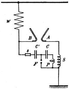 |
| Fig. 12. Siemens-Schuckert Lightning Arrester. |
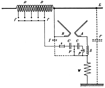
advantage that each condenser has to stand only part of the tension. For adjusting the auxiliary air-gap only the voltage of the condenser C has to be taken into account For this reason this latter arrangement may be used for higher tensions. Fig. 13 shows an arrangement having many different spark-gaps but requiring but one arrester. In this scheme no condenser is under tension for any length of time. If the arrester itself has not acted on the appearance of over voltage, it is at least probable one of the air-gaps, f, will get into action
 |
| Fig. 13. Lightning Arrester. |
so that the condensers C C1 are charged. This process of charging through a sparking distance cannot produce any considerable e.m.f. since the capacity of the condensers may be very small and are connected in series with the damping resistance W. Owing to the sensitive adjustment of the air-gap F of the oscillating circuit the condenser C begins to discharge at the beginning of the condenser charge, so that the arc, therefore, begins to discharge at once. The e.m.f of the secondary S does not any longer discharge through the oscillating circuit itself; since, however, the object of the relay is not to enlarge the gap but to start the discharge, a very small capacity Y is sufficient to cause a higher e.m.f. to be established between the horns of the arrester than that for which the arrester was adjusted. By this means the machine is protected by the high self-induction of the choking coils. There remains, however, the greater capacity T between the line and earth in series with the arrester and the resistance W which offers an easy return path for the oscillations passing from S to the arrester.
·
·
