[Trade Journal]
Publication: Electrical World
New York, NY, United States
vol. 11, no. 4, p. 42, col. 1-3
Electric Transmission of Energy by Oerlikon
Machines.
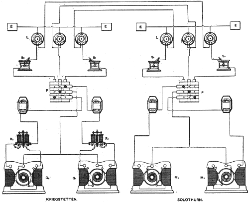
Our columns have already contained an account of experiments made at Zurich, Switzerland, with Oerlikon dynamos, designed to transmit the power of a waterfall a distance of five miles from Kriegstetten to Solothurn. These experiments were made by a committee of engineers and scientific men, with a view to ascertain the total commercial efficiency of the transmission plant; but as the machines were in this case placed side by side, the results could only be taken as approximately correct. It is evident that, in such an arrangement of machines and resistances erected within the limits of a covered workshop, the insulation of the circuits presents no difficulty whatever, whereas in the actual installation, when many miles of overhead wires must be used, the insulation becomes a matter of some difficulty, and atmospheric influences may also have some effect upon the performance of the plant. These considerations induced the makers to arrange for some further trials with the plant as actually installed. A committee was appointed, under the presidency of Professor Amsler, of Schaffhausen, the well known inventor of the planimeter, and other well-known gentlemen were members, among them Prof. Weber of the Zurich Polytechnic School. This committee have just issued their official report on the trials made on the 11th and 13th of October last with the plant as actually installed. Before quoting the results of these trials, it will be well to briefly refer to the general arrangement of this installation. At Kriegstetten there is a water power available, representing about forty actual horse-power, and the problem was to carry as much of this power as possible to a mill in Solothurn, the distance being 4 3/4 miles as the crow flies; but, allowing for deviations, the length of each circuit may be taken as about five miles. There are at Kriegstetten two generating dynamos, and at Solothurn two motors, coupled up on the three-wire system, as shown in the above illustration taken from Industries. Each dynamo weighs 8 tons 12 cwt., and has a Gramme armature 20 in. diameter and 14 in. long, the normal speed being 700 revolutions per minute; Referring to the diagram of connections, G1 and G2 are the generators at Kriegstetten, and M1 and M2 are the motors at Solothurn. R1 and R2 are electro-magnetic switches which automatically come into action and short circuit the exciting coils in case of the current rising beyond a certain limit. This provision was introduced in order to guard against the destruction of the generator in case a short circuit should take place somewhere in the line. The current from each of the generators passes through an ammeter and then to a plug switch-board P. to which is also connected the balancing wire joining the negative brush of G2, with the positive brush of G1. The balancing wire is then carried direct to the middle one of the three lightning arresters L. and then to the middle wire of the line, while each of the outside wires is led through a liquid switch S1S2 then to a lightning arrester, and to the line. Each lightning arrester consists of a circular metal disc, the edge of which is provided with projecting teeth, and situated in a concentric metal ring, the internal circumference of which is also provided with teeth, but not touching the teeth of the disc. All the discs are connected with a common earth wire and two earth plates E E. The same provision against lightning is made at the motor station. The switches S1 S2 are of peculiar construction, and consist of a vessel containing a conducting liquid and a perforated metal ball dipping into it. When the current is to be switched off, the handle is turned so as to raise the ball out of the liquid: but the circuit is not immediately interrupted, since the liquid within the balls issues in fine streams out of the perforations, and so maintains the connection for a short time after switching off. As the liquid in the ball gets exhausted, and the streams become thinner, the resistance of the liquid Connection is gradually increased to infinity, and thus causes the current to gradually diminish to zero. The line wires are supported on Johnson & Phillips' patent fluid insulators and the average span is about 130 ft.
 |
| Transmission of Power by Oerlikon Machines. |
Two sets of experiments were made. On the 11th of October only one generator and one motor were tested, while on the 12th of October both generators and both motors were tested. In the latter test the balancing wire was cut out of circuit as of no importance when as in these experiments, it was quite easy to regulate the load of each motor so as to fairly divide the work between them.
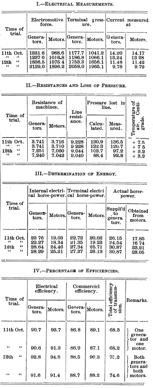
Electrical measuring instruments were fitted up at both stations in rooms sufficiently distant from the machinery so as not to be influenced by stray magnetism. The current was measured by large tangent galvanometers and Thomson mirror galvanometers, standard cells, and potentiometers were used to measure the pressure. The object in measuring the current at both ends of the line was to ascertain whether any appreciable leak took place. In addition to these purely electrical measurements, observations were made at the generator station regarding the water level in the head and tail race of the turbine, the position of the regulator on the latter, and the speed of the dynamos and turbine. After the transmission trial on the 11th of October was completed, the armature of the dynamo was taken out and replaced by a plain spindle provided at the end with a brake. The turbine was then started again under exactly the same conditions as were noted at the previous trial, and the power absorbed by the brake was measured. The comparison between the power thus measured and the electrical energy given out by the generator is evidently the commercial efficiency of the latter. On the following day both generators and both motors were tested in the same condition as prevails in actual practice, with the only exception that, as already mentioned, the balancing wire was cut out of circuit. This alteration, which could obviously not increase the efficiency of the whole system, was made to simplify the measurements. The power absorbed by the generators was computed on the basis of the previous day's trial from the observed conditions under which the turbine worked, while the power developed by the motors was on both days directly ascertained by means of a friction brake fitted to a first motion shaft common to both motors. A small correction was made for the power absorbed by this shaft when running idle. The following tables give the results as published by the committee:
 |
An inspection of these figures will show that there is practically no loss of current by leakage on the line. In some cases the current measured at the motor station is slightly below that measured at the generator station; but the discrepancy is exceedingly small, and evidently due to personal or instrument errors, since in some other cases the current received by the motors appears to be even slightly larger than that sent out by the generators, which is obviously impossible. The second table also shows the influence of the air temperature upon the total resistance. The third table gives the power, and the fourth the efficiencies in percentages. It will be noticed that when one generator and one motor only were used, the commercial efficiency was slightly over sixty-eight per cent.; but when both generators and both motors were used, this efficiency rose to about seventy-five per cent., which is clearly due to the higher voltage employed.
