[Trade Journal]
Publication: Electrical World
New York, NY, United States
vol. 11, no. 13, p. 161-162, col. 3,1-2
Overhead Circuits for Long-Distance Telephony.*
BY M. J. BANNEUX (CHIEF ENGINEER OF THE BELGIAN TELEGRAPHS).
For long-distance telephony a metallic circuit is an absolute necessity, as with a single wire and an earth return it is impossible to avoid the noises due — first, to earth currents; second, to induction from neighboring wires; third, to the '"picking up " of the currents from other circuits in the vicinity working also with earth returns. As an example of the last the author mentions an overhead wire in Brussels which made earth some fifty yards from a Morse instrument. The two wires ran at right angles to each other, so that there could be no appreciable induction between them, yet every Morse signal could be heard on the telephone line.
 |
| Fig. 1. Long Distance Telephone Circuits. |
The best method of stopping cross-talk, due to leakage, is, the author considers, the English method of using good insulators and joining all their iron supports to an earth wire at each station; most of the leakage current then gets to the earth instead of into the other wires.
 |
| Fig. 2. Long Distance Telephone Circuits. |
Induction from wire to wire is the other béte noir of telephonists, and to it many operators attribute cross-talk which is really due to leakage. It is true, however, that in foggy climates it is very difficult to determine which is the real offender.
The effect of one wire on another is represented approximately by the formula,
 |
where m is the coefficient of mutual induction, l the length of the two wires running parallel, and d their distance apart. The general solution of the difficulty of induction, whatever may be the inducing causes, is to use two wires in a complete metallic loop instead of a single wire and an earth return, and to so arrange them that the sum of the inductions of neighboring telegraph or telephone wires shall be exactly the same on both the wires of the loop. This principle was patented by Bell in 1877, and its efficacy was proved by Hughes in 1879.†
It was applied by Brooks, of Philadelphia, to cables, by twisting the two wires of the loop together.
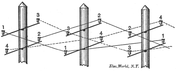
If a line of poles only carries one telegraph wire and a looped telephone wire it is very easy to obtain equal induction on both wires of the loop; all that is necessary is to run the telegraph wire parallel to its neighbors and equidistant from both of them. The telegraph wires, however, in practice are numerous, and vary in number from section to section, and the telephone wires cannot be arranged so as to be equidistant from each particular telegraph wire. In this case it is necessary to adopt a method similar to that employed for cables, namely, to twist the wires together in long helices. Prof. Hughes suggested a plan for doing this in 1879, which was carried out by Messrs. Moseley & Sons near Manchester. Since 1881 the English post-office have used the wiring shown in Fig. 1 for the trunk wires for joining two towns. It two trunks have to be run on the same line of poles they are arranged as in Fig. 2. Galvanized iron lines on this system are at work between Manchester and Liverpool, 30 miles; Newport and Cardiff, 13 miles; Glasgow and Greenook, 25 miles; Glasgow and Edinburgh, 36 miles; London and Brighton, 54 miles, etc., etc.
 |
| Fig. 3. Long Distance Telephone Circuits. |
In June and July, 1883, the Belgian Government established communication between Antwerp and Brussels, which towns, by the way, were the first two on the continent which were joined by the telegraph in 1846. The trunk was run along the railways, using No. 16 S. W. G. phosphor-bronze wire, about 16 lbs, per mile.
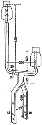
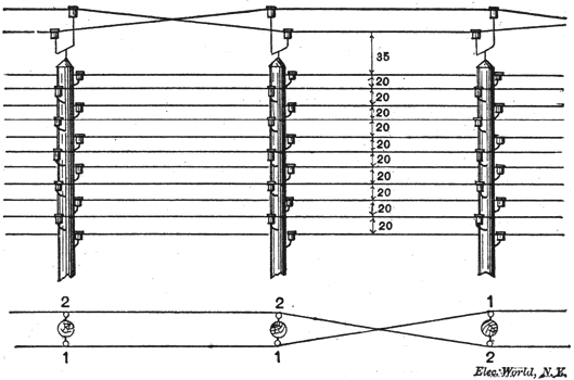
The posts were not provided with cross-arms, so the wires were run on the special brackets, which were fixed on the top of the posts as shown in Figs. 3 and 3A. The line was remarkably quiet; a slight fizzling was heard at times, but conversation could be carried on as easily as between two subscribers in one town. Both Blake and Van Rysselberghe transmitters were used.
 |
| Fig. 3a. Long Distance Telephone Circuits. |
Van Rysselberghe's system was applied to the Belgian telegraph lines during 1884, and the first line opened to the public in October. At the present moment (Nov. 1887) there are some 1,800 miles of double wire used simultaneously for telegraph (Morse and Hughes) and for telephone inter-urban trunk lines.
The author then proceeds to describe the Paris-Brussels line. It was agreed between the representatives of the two countries that the line should be a closed metallic circuit of No. 11 S.W.G. high conductivity wire, to be run on the telegraph posts on the railway, and to be protected from induction as far as possible, the means to be employed to do so being left to the respective governments. The whole air line, 195 miles, was run in three weeks in the months of December, 1886, under great difficulties from bad weather. The length of the Belgian section is 48 miles. It starts from the Bourse in Brussels, and the Paris end is joined on to the Bourse there by underground lead cable 3 miles long.
 |
| Fig. 4. Long Distance Telephone Circuits. |
The Belgian part of the line is run in phosphor-bronze; the French is silicium bronze. Great care had to be taken with the insulators, as good insulation was as important as freedom from induction. The system of running on the top of the poles, which had been found so satisfactory on the Brussels-Antwerp line, was adopted. But, rightly or wrongly — the author thinks the latter — the wire running department objected to the idea of the wires crossing vertically in the air, on the score of danger of wind contacts. (By a vertical cross is meant that between two poles the two wires remain respectively on the same sides of the poles, but exchange their levels, as opposed to a horizontal cross, when they retain the same respective levels, but exchange sides.)
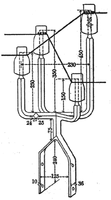
A four-branch bracket, Fig. 4, was therefore used, so that all vertical crossings take place at the posts. The four insulators are undesirable, as every additional insulator offers an additional chance of leakage. It was found to be sufficient, however, between stations to put in a four-way bracket, and reverse vertically at every thirtieth or thirty-fifth post, and between these to re verse horizontally backwards and forwardsnt every sixth or seventh span, using brackets of the type already shown in Fig. 3, Fig. 5 is a diagram of a portion of the line passing by the railway station at Mons, where the wires are crossed horizontally at more frequent intervals. This method does not entail cutting the wires, so that there are no more joints than in direct running.
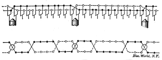 |
| Fig. 5. Long Distance Telephone Circuits. |
The line was first opened on February 24, 1884, and the public can judge whether it works satisfactorily or not. As to the engineers of the two administrations, accustomed as they are to almost daily faults on a telegraph line of such a length, they are delighted with the perfect way it conducts itself. The greater part of the faults which have occurred have been in Brussels, where the house painters have occasionally short-circuited the overhead wires. The same wires are used simultaneously for telegraphy on the Van Rysselberghe system. The insulation and conductivity of the line were proved when, one winter's day, all the other telegraph wires having become unusable, the Hughes instrument got through to Paris at full speed on the telephone wires.
The two wires of the line must be alike in material and insulation. The line ceased to be silent, for example, when a Bell telephone was interposed at the frontier in one of the wires, or if one of them touched a tree branch or a damp wall.
* Abstract of a paper read before the Société Belge des Electriciens.
† Journal Soc. Tel. Eng., Vol. VIII., 1887.
