[Trade Journal]
Publication: Western Electrician
Chicago, IL, United States
vol. 31, no. 5, p. 71, col. 1-3
Pike's Peak Power Company's
Transmission System.
A hydro-electric power development and transmission enterprise of more than ordinary interest is being carried out in the vicinity of Cripple Creek, Colo., by the Pike's Peak Power Company. This corporation, which is controlled by the Woods Investment Company of Colorado Springs and Victor, Colo., owns land on 12 miles of Beaver Creek and its two tributaries, West and East Beaver Creeks, in Teller and Fremont Counties. These streams are noted for excessive difference in elevation in short distances, and produce sufficient water to make of them valuable waterpower properties.
One of the power stations planned by the company is located on West Beaver, in Fremont County, 2 1/2 miles up the stream from the junction of East and West Beaver, and is known as Station A. The dam and reservoir are 5 1/2 miles east of Victor. Here is located what is said to be the largest steel-faced, granite backfilled dam on record to date. The structure is 405 feet in length along the cap, 220 feet in length of base, 148 feet in cross-section at base and 20 feet in cross-section at cap. To obtain the amount of rock and material necessary to construct this dam, the top of Vesuvius Butte was blown off by an immense, dynamite explosion in December, 1899. An illustrated description of this interesting operation, by means of which 110,000 cubic yards of rock was obtained, was given in the Western Electrician of February 24, 1900. The reservoir formed above the dam has a surface area of 130 acres and holds 102,000,000 cubic feet of water.
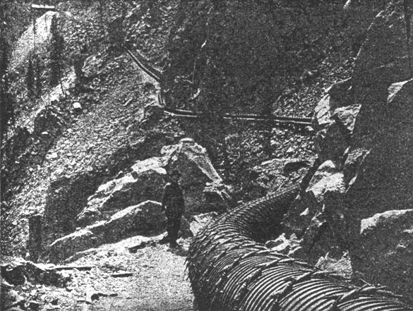
Water is taken from this dam through a wood stave pipe, 23,200 feet long and 30 inches in inside diameter. The pipe is constructed of 1 1/2-inch redwood stave, banded with one-half-inch steel bands and cast-iron lugs. The pipe line extends over fearfully rough country, about half of the grade being through original granite formation; many curves are on less than 100 feet radius, and there is one compound curve of 35 feet. A typical view of the line is shown in Fig. 1. The wood pipe passes through the Skaguay tunnel, which is 1,535 feet in length, located 21,000 feet from the dam.
 |
| Fig. 1. Wood Stave Pipe Line. Pikes Peak Power Company's Transmission System. Border |
From a point 200 feet below the Skaguay tunnel, where the static pressure reaches 220 feet, the line consists of steel pipe 29 inches in diameter in various thicknesses of plates, ranging from one-fourth to three-fourths inch, as required to meet the internal pressure with an ample factor of safety. The total length of steel pipe, including the receiver, is 2,900 feet, and it is on an incline averaging 38 per cent. It passes over grades constructed through a tougher granite formation in respect to roughness than ever was encountered in railroad construction in Colorado. At one point it passes through an inclined tunnel 335 feet in length, just above which is a, bridge 70 feet in height, both being on 40 per cent. gradient, and at various points there are extremely deep open cuts. From the south end of the Skaguay tunnel the pipe line is entrenched in the grade on which is constructed a three-foot railway leading from the Skaguay tunnel to the power house, its grade being 1,163 feet vertical in 3,100 feet horizontal. This road is the only means of access to the power house. The cars are operated by a double-hoisting engine.
The upper terminus of the railroad lies under a vertical ledge 70 feet in height, and all machinery, apparatus and materials of all kinds, were lowered by boom and derrick, taking loads from the wagons at the upper landing and lowering them 70 feet over the ledge to the cars. The loaded cars were lowered by means of the friction brake on a hoist, which was equipped with a three-fourths-inch steel cable: 1,400 tons of building materials passed down this peculiar railroad.
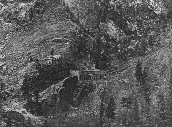
The power house is 38 by 98 feet in size, with two side wings of 16 by 48 feet each, and is located (Fig. 2) on the summit of a granite projection surfaced off true to grade. The building is constructed of brick, with a corrugated-steel arch roof, covered with concrete, tar and gravel; it has a concrete floor and is absolutely fireproof. It is provided with a 10-ton traveling crane.
The hydraulic apparatus was manufactured by the Pelton Water Wheel Company of San Francisco. Each unit consists of two steel disk wheels 66 inches in diameter keyed to the same shaft and working in the same wheel house. The connection of the waterwheel and generator shafts is effected by the hub of a 7,000-pound steel cast balance wheel, banded with a rolled-steel tire band four inches in thickness. The wheel is seven feet in diameter. The nozzles used to develop the required power under the 1,160 feet of effective head obtained at the station require to have a diameter of only one inch to furnish 236 horsepower, including losses. Deflecting nozzles are used and the regulation is of the Armstrong type.
The electrical generators now in operation at Station A are four 400-kilowatt General Electric machines, with rotating fields. They deliver a three-phase, 30-cycle current at 600 volts on 450 revolutions a minute. Two four-pole, 30-kilowatt exciters furnish current at 70 volts, each giving sufficient exciting current for all four generators when working at full load. The waterwheels have an efficiency of 83 per cent. and the generators of 94 per cent.
The switchboard apparatus is especially liberal in design, and comprises one exciter panel, four generator panels, two distributing panels, two high-tension panels and one paralleling or synchronizing panel. The panels are made of Vermont marble and have a full complement of indicating and recording instruments, switches and regulating apparatus. The transformers are six 250-kilowatt, air-blast of the General Electric make, having 600 volts on the primaries and 12,600 on the secondaries.
| |||
| Fig. 2. Power House and Surroundings. Pikes Peak Power Company's Transmission System. |
Since the early operation of this station, it was found necessary to install some thorough system for combined arc and incandescent lighting, which has been fully accomplished by the introduction of two 200-kilowatt, compensated, three-phase generators, 60 cycles, with their full equipment. These generators have 12 poles and operate at 600 revolutions a minute. Each generator contains its own independent 12-pole exciter, built directly on the revolving-field shaft. These machines are also directly connected to impulse-type waterwheels.
The line transmission from Station A to the center of distribution at the Gold Coin Mine at Victor includes a distance of eight miles by pole line. The circuits consist of three No. 4 B. & S. power wires, and the lighting circuits of three No. 6 B. & S. wires, which are ample to deliver 1,600 kilowatts at less than a five per cent. energy loss These lines are transposed at intervals of one-half mile along the line. The poles also carry for telephone purposes two No. 10 galvanized iron weatherproof wires, transposed each 120 feet. Porcelain insulators, 5 1/2 inches in diameter are used. The line voltage is 12,600, both on 30 and 60-cycle lines.
The sub-station adjoins the Gold Coin ore house in Victor and contains nine 50-kilowatt oil transformers, changing the current to 115 and 460 volts secondary for lighting and power distribution. A set of three 50-kilowatt oil transformers with 350-volt secondaries, operates a 120-kilowatt rotary converter, furnishing current for a locomotive in the United Mines transportation tunnel for ore hauling, and also for Bull Hill tunnel haulage. High-pressure distributing lines leave the sub-station in various directions and are carried to different mines in the vicinity for power and lights and to the towns of Cameron, Gillett, Goldfield, Anaconda and Elkton for lighting purposes.
It is planned to construct a second station, known as Station B, at a point 200 feet above the forks of the East and West Beaver Creeks. The hydraulic pressure at this station will be 1,257 feet, or 544 pounds per square inch, and a total of 5,500 horse-power will be capable of development. R. M. Jones, engineer and general superintendent of the Pike's Peak Power Company, describes the present equipment of the company in a recent issue of the Engineering Record. He says it is the purpose of the company to construct an independent transmission line from Station B to Station A and possibly an independent line to the distributing stations in Victor, including the connections through Station A, thus permitting the use of the entire energy of both stations to work in parallel over either station's lines or to work each station independently, as desired. It is also proposed that transmission lines will be extended from these stations to other localities within reach. Thus, with two complete pipe lines, pole lines and generating-station systems, the most unquestioned reliability may be counted upon. It is also the intention of the company to install a third station on the combined Beaver streams at a point near the mouth of the canyon and approximately two miles below Station P., to be known as Station C. Here the difference in elevation is but 373 feet, but as the volume of water will probably reach 50 second feet, this would develop 2,100 horse-power, less losses. The company owns also an excellent reservoir site on East Beaver at 1,700 feet elevation above Station B and but 2 1/2 miles distant, which reservoir may be developed to excellent advantage in the near future.
