[Trade Journal]
Publication: Electrical World and Engineer
New York, NY, United States
p. 119
Power Transmission in the Pike's Peak Region.
BY R. M. JONES.
THE Pike's Peak Power Company, whose general offices are at Victor, Colo., was organized in 1899, under the laws of Colorado. The company during that year purchased ranch property, placer claims and reservoir sites on West and East Beaver creeks, in Teller and Fremont counties, and also located, developed and patented placer claims along these streams. At this date it owns all the lands along these streams, including reservoir sites, and all water power privileges, over a distance of 1 1/2 miles on Beaver, 7 miles on West Beaver and 3-1/2 miles on East Beaver. These streams are noted for their excessive difference in elevation in short distances, and produce sufficient water to make of them valuable water power properties. One of the power stations contemplated by the company is completed, and has been in operation during the past year, and known as "Station A," located on West Beaver, in Fremont County, 2-1/2 miles up the stream front the junction of East and West Beaver. The completion of this station has also accomplished much of the development and actual construction necessary for stations "B" and "C," by way of reservoir capacity and pipe line delivery of the water, serviceable to the two lower stations after having been used through "Station A."
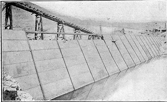
DAM AND RESERVOIR.
The dam and reservoir are located 5-1/2 miles east of Victor. Here is located the largest steel-faced, granite-back filled dam on record to date (Figs. 1 and 2). The structure is in length 405 feet along the cap, 220 feet length of base, 148 feet cross-section of base, and 20 feet cross-section of cap. The upper slope, being the steel face, is 30 degrees front the vertical, and the lower slope 50 degrees vertical. The height of the dam from bed rock to the top of the sixteenth plate (being the spillway) is 70 feet. The spillway is 40 feet wide, cut in granite formation and passes around the north west end of the dam. The granite back fill, to which the steel plate is laid, is carefully laid in "dry wall" of heavy granite boulders, usually 20 to 80 cubic feet each, as broken by heavy blasting, with loose, fine granite filling the intervening space.
| |||
| Fig. 1 - Dam for Pike's Peak Power Transmission. |
| |||
| Fig. 2 - Dam for Pike's Peak Power Transmission. |
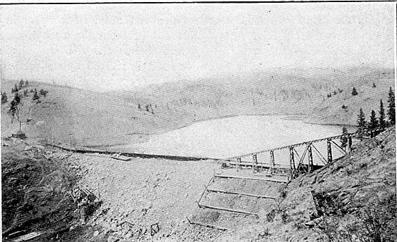
The steel plate is built up of sheets 5 x 15 feet and 1/2 inch in thickness for the bottom, 8 plates in height. Continuing, the plate is reduced in thickness to 3/8 of an inch, and finally at the cap it is 1/4 of an inch. The entire sheet is riveted with horizontal butt straps, and 4 x 5 x 1/2 inch angle bars are placed vertically the entire height of the dam across each interval of 15 feet for the entire length. The 5-inch leg of each pair of angle bars project into the reservoir and constitutes a standing joint seam, with an iron liner 3 x 2 inches riveted between the extreme outer points of these angle bars, thus making a thorough expansion joint for each section of 15 feet. The bottom and end connection of the entire sheet is concreted into a deep channel-way, quarried out of bed rock, and the bottom terminates in two pairs of 5 x 8 inch angle bars, which are riveted through the plates. The end connections are prepared in exactly the same manner, but are applied vertically. The quarrying of the bed-rock channels was carried out horizontally in each case to a point rising to an elevation, and thence the rise was made abruptly in terrace form. The entire sheet is riveted up and calked in the same thorough manner as in boiler practice. A space of six inches was left between the steel plates and smooth surface of the granite back fill. This narrow space is taken up by sand, gravel and sedimentary deposit, the filling being applied with ample water and permitted to dry before water pressure was allowed to enter. The reservoir has a surface area of 130 acres, and holds 102,000,000 cubic feet of water.
| |||
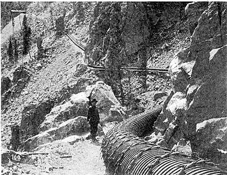
| Fig. 3 - Section of the Stave Pipe Line. |
| |||
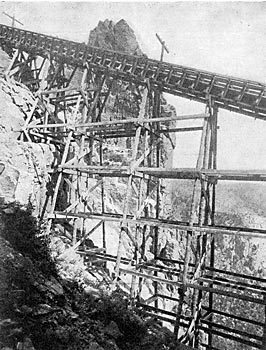
| Fig. 4 - Forty Per Cent Trestle. |
WOOD AND STEEL PIPE LINE.
Water is taken into the wood stave pipe through a "Grizzley" 240 feet long, perforated, giving 3o times greater area than the pipe. The "Grizzley" and the main pipe line are connected to the steel facing of the dam by steel angle connections. The wood pipe is 23,200 feet long, 30 inches inside diameter, and is of 1-1/2-inch redwood stave, banded with 1/2-inch steel bands and cast-iron lugs. The bands are spaced at intervals along the pipe at all distances between 2-1/4-inch and 8-inch centers as necessary for resisting the internal pressure; variations being caused by various inverted syphons along the line, two of which reach 215 feet pressure. This pipe line extends over fearfully rough country, about half of the grade being through original granite formation, many curves were on less than too feet radius, and one compound curve was 35 feet. The wood pipe passes through the Skaguay Tunnel, which is 1,535 feet in length, located at 21,000 feet from the dam.
From a point 200 feet below the Skaguay Tunnel, where the static pressure reaches 220 feet, the line consists of steel pipe 29 inches in diameter in various thicknesses of plates, ranging from 1/4 to 3/4 of an inch, as required to meet the internal pressure with an ample factor of safety. The total length of steel pipe, including the receiver, is 2,900 feet, on an incline averaging 38 per cent. It passes over grades constructed through a granite formation, tougher in respect to roughness than ever was encountered in railroad construction in Colorado. At one point it passes through an inclined tunnel 335 feet in length, just above which is a bridge 70 feet in height, both being on 4o degrees gradient, and at various points there are extremely deep open cuts. From the south end of the Skaguay Tunnel the pipe line is entrenched in the grade on which is constructed a 3-foot gauge railway leading from the Skaguay Tunnel to the power house, its grade being 1,165 feet vertical in 3,100 feet horizontal. This road is the only means of access to the power house. The cars are operated by a double-hoisting engine.
The upper terminus of the railroad lies under a vertical ledge 70 feet in height, and all machinery, apparatus and materials of all kinds were lowered by boom and derrick, taking loads from the wagon at the upper landing and lowering them 7o feet over the ledge to the cars, from which point the loads were lowered by friction brake on the hoist equipped with a 3/4-inch steel cable; 1,400 tons of building materials passed down this peculiar railroad. Views of the pipe line, trestle, etc., are given in Figs. 3 and 4.
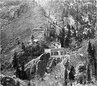
POWER STATION.
The power house, "Station A" (Figs. 5, 6, 7 and 8) has dimensions 38 x 98 feet, with two side wings 16 x 48 feet each, and is located on the summit of a granite projection surfaced off true to grade. The building is constructed of brick, with steel, corrugated-steel arched roof, concrete, tar and gravel covered; concrete floor, and is absolutely fire-proof. The building is provided with a 10-ton traveling crane. The hydraulic apparatus was manufactured by the Felton Water Wheel Company, of San Francisco. Each unit consists of two steel disc wheels 66 inches in diameter, keyed to the same shaft, and working in the same wheel house. The base frames are built up in box pattern of the same type and general design as the generators, to which they are connected. The frames of the water wheels and generators are faced for accurate, rigid connection to each other by bolts and dowels. The connection of water wheel and generator shaft is effected by a 7,000-pound steel cast balance wheel, banded with a rolled-tire steel band, 4 inches in thickness. The wheel is 7 feet in diameter, and its hub forms the connection on the waterwheel shaft, and one-half of the hub forms the other half of face coupling keyed to the armature shaft, making an accurate and rigid direct connection of the shafts of the two machines.
| |||
| Fig. 5 - General View of Power House and Mountains. |
| |||
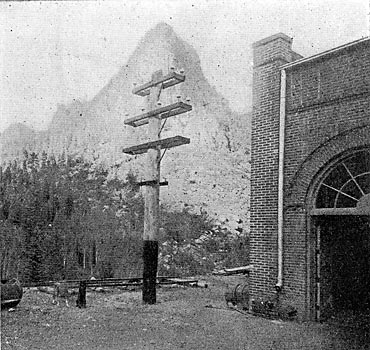
| Fig. 6 - Mason's Peak and Power House. |
The nozzles used with which to produce the required power, as applied under 1,160 feet effective head obtained, require only a diameter of one inch for 236 horse-power, including losses. The nozzles for each unit vary in diameter, one having the capacity of the generator, and the corresponding nozzles for the other wheel in the same unit being somewhat reduced. Each wheel in each unit will produce power for the full capacity of the generator connected. In operation, however, it is customary to install such a varied diameter or capacity of nozzles as to permit the operation of the full capacity of the load demand from time to time by the operation of nozzles under full pressure, and but slight loss in water due to regulation for low loads.
 |
| Figs. 7 and 8 - Plan and Elevation, Pike's Peak Plant. |
The nozzles are of the deflecting type, and work under full pressure at all times, which explains the variation in the diameters of the nozzles. The regulation is of the "Armstrong" type, owing to the fact that automatic regulation under existing conditions could be only a failure, without reference to the class applied. Due provision has been taken to extend the actual control and regulation of-each unit to a point directly in front of the switchboard panel belonging to that unit. The receiver runs longitudinally through the building under the steel-concrete floor. The discharge or tail-race water returns directly under the receiver to the south or lower end of the building, at which point it will later unite with water conducted from a point far above "Station A," where a catcher-dam is to be constructed, and the water diverted from the Beaver stream channel. There being a considerable accumulation of water between the dam and "Station A," it is the purpose of the company to unite the waters through "Station A" with the accumulation in the stream, and conduct the combined waters through a pipe line to a point zoo feet above the forks of the east and west Beaver Creek, at which point will be constructed "Station B." There will be built a small pipe line up the east Beaver to the same static level as the tail-race water of "Station A." The waters of both pipe lines will be united before entering the receiver. The pressure of "Station B" will be 1,257 feet, or 544 pounds pressure per square inch. With the added accumulation of water in the west Beaver branch, 3,500 hp will be obtained, and from the east Beaver branch about 2,000 hp, all of which may be developed at "Station B."
| |||
| Fig. 9 - Interior View, Pike's Peak Power House. |
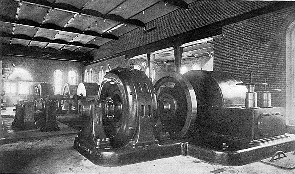
ELECTRICAL EQUIPMENT.
The electrical generators now in operation at "Station A" (Figs. 9 and 10) are four 400-kw General Electric machines, three-phase 30 cycles, 600 volts, with stationary armatures and rotary fields, making 450 r. p. m. As already mentioned, the generators are driven directly connected to the water wheels. Two 4-pole exciters, direct-current machines, have a capacity of 30 kw each, running at 675 r. p. m., producing an exciting current at 70 volts each, giving sufficient exciting current for all four generators while working at full load. In reference to the efficiency of the water wheels, it may be stated that they were guaranteed to develop 83 per cent. of power on their shafts at full load when the nozzles are in normal position. In considering the efficiency of the water wheels, the General Electric Company's generators were assumed to have a commercial efficiency of 94 per cent. at full, non-inductive load. Therefore, with every 33,000 foot-pounds of water, the wheels will produce in current one indicated horse-power less 17 per cent. loss in the wheels, and 6 per cent. loss in the generators, delivering 78-100 horse-power, or 582 watts, from the brush-holder terminals of the generators. These efficiencies have been fulfilled by tests. All water connections are tested to 800 pounds pressure to the square inch. In making the efficiency tests, measurements are made through the standard weir commonly used in the United States, verified by spouting tests by working water through the nozzles of known diameters. The developed power is measured by the best electrical instruments obtainable.
The switchboard apparatus (Fig. 11) is especially liberal in design, and is made up of one exciting current panel, four generator panels, two distributing panels, two high-tension panels and one paralleling or synchronizing panel. Each panel is made of Vermont marble, 62 x 36 inches, with a sub-base 28 x 36 inches, and 2 inches in thickness, with a complete equipment of indicating and recording instruments, switches and regulating apparatus. The main line switches from each machine are operated independently either for power or light. The circuits are arranged so that any or all of the machines may be applied on either circuit. The transformers are six 250-kw air blasts, of General Electric make, having 600 volts on the primaries and 12,600 on the secondaries. The 12 complete sets of lightning arresters are of the same make. The cable connections between the generators and switchboard, and from the switchboard to the transformers are all highly insulated, paper, rubber and lead, and laid in conduits in the concrete floor. Since the starting up of this station, it was found necessary to install some thorough system for combined arc and incandescent lighting, which has been fully accomplished by the installation of two 200-kw compensated, three-phase generators, 6o cycles, with their full equipment. These generators are 12-pole, and operate at 600 r. p. m. Each generator contains its own independent D. C. exciter, 12 poles, built directly on the revolving field shaft. These machines are also directly connected to impulse type water wheels.
LINE TRANSMISSION.
The line transmission from "Station A" to the center of distribution (at the Gold Coin Mine, at Victor) includes a distance of eight miles by pole line. The circuits consist of three power wires No. 4 B & S. gauge, and the lighting circuits of three No. 6 B. & S. gauge, which are ample to deliver 1,600 kw at less than a five per cent. energy loss. These lines are transposed at intervals of each one-half mile along the line. The poles also carry for telephone purposes two No. 10 galvanized iron weather-proof wires, transposed each 120 feet. The insulators were furnished by R. Thomas & Sons Company, of East Liverpool, Ohio. They are 5 1/2 in:hes in diameter, of porcelain, and each is made up of three independent cups. In manufacture they were subjected to a 40,000-volt salt test. The line voltage is 12,600, both on 30 and 60 cycle lines.
SUB-STATION AND DISTRIBUTION.
The sub-station is a brick, steel, concrete structure, fire-proof, adjoining the Gold Coin ore house, in Victor. All transmission circuits enter this building where the current is transformed through nine 50-kw oil transformers, General Electric type, 12,000 volts primary and 460 volts secondary, for local lighting distribution connected in the Y four-wire system, also, for local power work.
There is installed in addition a set of three 50-kw oil transformers, 12,000 to 350 volts, which operates a 120-kw rotary converter, which drives a locomotive in the United Mines Transportation Tunnel, for ore hauling from first level of the Gold Coin mine to the Economic Mill; and for the Bull Hill Tunnel haulage. High pressure distributing lines leave the sub-station in various directions (after first passing through 20,000-volt oil switches, making each line independent) to Economic Mill, where about 300 horse-power is delivered. To the Beacon Hill there is a power distribution for hoists, power and lights. To the Deadwood Mine is a line for a 100-hp air compressor, and a secondary 46o volts power circuit reaches Independence, Altman and the Wild Horse districts. Another primary line reaches Cameron and Gillett, after first passing through Goldfield, all for lighting service, and distributed in each of these towns through their local transformers connected in delta.
Two additional primary distributing lines reach Anaconda, where independent lighting and power are distributed to the town of Anaconda and the various mines in that vicinitythe Morning Glory, Doctor Jack-Pot and others. These lines also reach Elkton on the way to Anaconda, where lighting is also distributed. The Pike's Peak Power Company has just begun, in fact, to develop its various points of distribution. It has already reached all the places and properties mentioned with a good, series alternating system of 60 cycle arc lighting, which is distributed in three directions through one 70 and one 50-arc constant-current transformer, located in the Victor sub-station.
PLANS FOR EXTENSIONS.
It is the purpose of the company to construct an independent transmission line from "Station B" to "Station A," and possibly an independent line to the distributing stations in Victor, including the connections through "Station A," thus permitting the use of the entire energy of both stations in parallel over either station's lines, or to work each station independently, as desired. It is also proposed that transmission lines shall be extended from these stations to other localities within reach. Thus, with two complete pipe lines, pole lines and generating station systems, the most unquestioned reliability of service may be counted upon. The distribution of light
·
·
[Missing text]
·
·
