[Trade Journal]
Publication: Western Electrician
Chicago, IL, United States
vol. 40, no. 16, p. 337-338, col. 1-3,1-2
Hydro-electric Power Development on
the Chicago Drainage Canal.
A large and in some respects unique hydro-electric power development is nearing completion on the Chicago Drainage Canal at a point about 1 1/2 miles south of Lockport, Ill., and something over thirty miles southwest of Chicago. The history of this power, plant dates, indirectly, to the time when the Sanitary District of Chicago was organized in 1890. It was then that the plans were laid for the construction of the Drainage Canal for sanitary purposes, now completed to Lockport and still being extended to a point beyond Joliet, some forty miles from Chicago. Primarily, the Drainage Canal was planned to afford an outlet for Chicago's sewerage system, so that Lake Michigan, the source of water supply, would not be contaminated, as would be the case in the natural order of events. Permission was obtained from the United States government to divert 10,000 cubic inches of water per second from Lake Michigan into the Chicago River, reversing the flow of the river. The construction of the canal involved many difficulties and numerous knotty engineering problems. All have been successfully solved, and, besides serving its sanitary mission, the big ditch is also, potentially, a model ship canal, which no one doubts will some day form part of a deep waterway between Chicago and the Gulf.
Since the Sanitary District was organized in 1890 $52,697,495 has been expended for construction and maintenance of the canal. Receipts have amounted to $53,171,199; this includes $35,688,266 from taxes, $17,030,000 from the sale of bonds, $382,424 from interest and $36,784 from the sale of land.
A few years ago the trustees and engineers of the Sanitary District began to see a source of income for the project if the large flow of water in the canal could be "harnessed" for the generation of electricity. The engineers worked out a plan for a large hydro-electric power plant, and three years ago work was commenced on the plant now nearing completion below Lockport.
While the electrical installation for this large plant is not yet sufficiently advanced to warrant a detailed description, a preliminary survey of the project will not be amiss. There are many features of interest about the plant, among them the power house itself, the dam, the ship lock and the great channel wall necessary to get a fall of 34 feet at the waterwheels. All these are of concrete or concrete and steel construction.
| |||
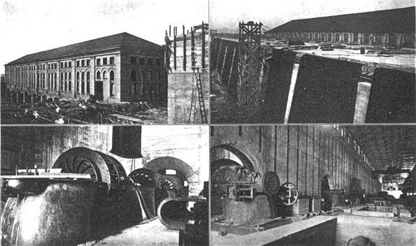
| (Left) Power House From Down-Stream Side, Showing Discharge Chambers. (Right) Power House From Up-Stream Side, Showing Straining Racks. (Left) One of the Turbines in Course of Erection. (Right) Interior of Power House. Showing Turbine Chambers Hydro-Electric Power Development on Chicago Drainage Canal, Near Lockport, Ill. |
When the waterpower project was begun the canal ended at the controlling works at the north line of Lockport. From this point there is a gradual fall to the south, and surveys proved that by slight excavation for a distance below the controlling works and the construction of. powerful concrete containing walls between which to conduct the water of the canal a sufficient fall could be obtained at a distance of 1 1/2 miles, and at that point the-generating plant was located.
It will be understood, then, that the concrete retaining walls, built to a height level with the controlling works dam, gradually rise in height from a few feet at the controlling works to 40 feet at the power site. Similarly the excavation grows less as the power site is approached.
The power house, controlling works and the ship lock, placed side by side, form the dam across the channel. The power house is 385 feet long, 70 feet wide and 47 feet high. The retaining walls of the channel are 40 feet high and therefore will bring the water level near the top of the building on the receiving side, giving a fall of 34 feet to the turbines, which furnish the power. These turbines are located in chambers at the floor level and discharge through chambers to the tail race.
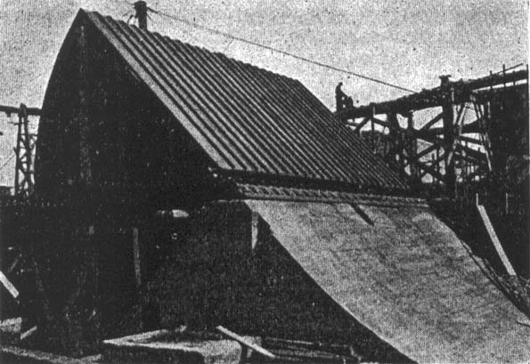
The movable-crest dam or controlling works joins the power house to the east. This part of the dam is for the purpose of regulating the flow of water in the canal. When the plant is completed the present controlling works at Lockport will be abandoned.
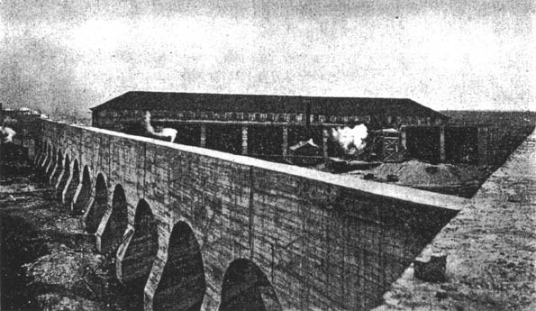
Joining the controlling dam to the east and completing the dam across the channel is the large lock for lowering boats to the lower level of the canal below the power site, to be used when the deep waterway project is completed. The concrete walls of the lock are 52 feet high at the lower end, and the lock is of sufficient size to admit the largest river steamers.
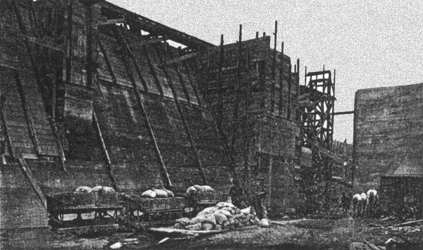
Built at an angle across the channel is a concrete guard protecting the forebay from floating ice. This wall diverts the ice to the controlling dam Within the forebay and protecting the wheel chambers from drift wood or other material which might get past the ice guard are a series of iron racks extending the length of the power house.
Everything about the plant is built on solid rock, and the various structures are made of concrete. All the stone required in the concrete mixing is obtained on the spot.
The power house is absolutely fireproof, no combustible material being used in construction. The building is designed to receive eight 4,000-kilowatt alternating-current generators and three exciter units of 250 kilowatts capacity each, the generators and exciters being each direct-connected to water-wheel units of the Wellman-Seaver-Morgan make. The generator turbines are each of 6,000-horsepower capacity and the exciter wheels 600 horsepower.
At present four of the generator units and two exciter sets are being installed. This will give an initial output of 20,000 horsepower, which will be available soon. Preparations are being made for setting up the fifth unit, and the other three will be installed as required, bringing the capacity of the plant up to 40,000 horsepower when completed.
The generators now being installed are of the Crocker-Wheeler make and are designed for three-phase 60-cycle alternating current at 6,600 volts. From this the current will be stepped up to 44,000 volts for transmission to the Chicago sub-station, where it will be transformed down to 12,000 volts for distribution to local points of use. At the local points, another transformation may be made to the desired voltage for any commercial lighting or power use. The large transformers of the present installation at the power house were furnished by the General Electric Company.
| |||
| Hydro-Electric Development on Drainage Canal Near Lockport. Movable-Crest Dam. |
The entire north half of the power house, 385 by 35 feet, is devoted to the generators and exciters, the waterwheel for each machine being located in a chamber adjoining. Traveling over the generator space is a 40-ton electric crane. The south half of the main building contains the switchboards, transformers, bus-bars, oil switches, circuit-breakers, lightning arrester-apparatus, etc. It has three floors or galleries.
The Chicago sub-station, quite similar to the power house in construction and design, is located at Western Avenue and the Drainage Canal. It is 124 feet long, 70 feet wide and 42 feet high. Here will be located the step-down transformers, special switching devices, switchboards, etc., with ample space for a complete duplication when required. From this building power will be distributed to the different local points.
Material is now being distributed along the canal for the transmission line to Chicago. The line will consist of two circuits of aluminum wire, either circuit having ample capacity to transmit the full load. Galvanized steel poles, 60 feet high, will be used, set in concrete foundations. The transmission lines will follow the canal from Lockport to Chicago, passing over the District's own lands through Romeo, Lemont, Sag, Willow Springs and Summit.
A safe margin in generator and transformer capacity, duplicate transmission lines, interchanging switching arrangements, together with all the most modern devices, have been provided for, and no expense has been spared to make the installation modern throughout, insuring absolutely reliable service.
| |||
| Concrete Wall to Deflect Ice From Forebay. Hydro-Electric Power Development on Chicago Drainage Canal, Near Lockport, Ill. |
| |||
| Concrete Wall of Lock for Ship Canal. Hydro-Electric Power Development on Chicago Drainage Canal, Near Lockport, Ill. |
The site of the plant is quite isolated; nevertheless, the scene is one of great activity. The work has required the greatest care and skill on the part of the engineers and contractors, and its completion in the near future will enable the trustees to deliver power in Chicago and vicinity at a cost undoubtedly much below that now entailed in either renting or manufacturing power under ordinary existing conditions.
The District is planning to extend the canal to a point below Joliet, where it is proposed to erect another plant similar to the one now nearing completion.
It is the denned purpose of the Sanitary District to supply the municipalities within its limits with such power as may now or later be required for their own use. The surplus power, now approximately 10,000 horsepower, will be sold to power users in general at a price lower than the cost of steam power. This power will be available at an early date at any point along the canal between Robey Street and Lockport, and at other points when applications are made therefor. The District is prepared to lease sites adjacent to the canal at points convenient for supplying this power, and with water for all uses of the manufacturer.
The trustees have expended about $3,000,000 on the water power development at Lockport since they began to carry out the plan three years ago. The planning and installing of the electrical plant and equipment have been under the direction of Mr. Edward B. Ellicott, electrical engineer of the District, who has also directed the entire development at Lockport. Mr. Isham Randolph is chief engineer of the Sanitary District and Mr. Robert R. McCormick is president of the trustees. The Western Electrician is indebted to Mr. Ellicott for the pictures accompanying this article.
