[Trade Journal]
Publication: Western Electrician
Chicago, IL, United States
vol. 41, no. 10, p. 175-176, col. 1-3,1
The Lockport-Chicago (Drainage Canal)
High-tension Transmission Line.
A high-tension transmission pole-line whose construction has been the subject of considerable interest among electrical engineers and others is nearing completion along the banks of the Chicago Drainage Canal between Lockport and Chicago. Near Lockport, as readers of the Western Electrician know, the water of the Chicago Sanitary District's drainage canal, fed by the reversed Chicago River from Lake Michigan, has a considerable drop to the Desplaines River, from which it finds its way to the Gulf. By the extension of the canal two miles beyond Lockport between great concrete retaining walls, which rise above the level of the surrounding country as the land slopes, away, a power-house site has been obtained which insures a 40-foot fall for the ultimate flow of 600,000 cubic feet of lake water.
The 32,000-kilowatt generating station at the site thus secured is now near completion and the primary installation of 20,000 horsepower will soon be available for use. A complete and illustrated description of this station appeared in the Western Electrician of April 20th. A considerable portion of the electric power from this plant will be transmitted to Chicago over one of the most substantial pole lines ever constructed.
The present article will be directed to a description of the unusually interesting construction of the pole line which follows the canal into Chicago and which includes some features that make it one of the most unique as to size and modern in design in the world. The difficulties in erecting the massive steel poles were heightened by the changing characteristics of the country along the 40 miles of the transmission line, which runs on the bank of the canal between the water and the spoil pile. The channel has been cut through solid rock from Willow Springs, Ill., to the Lockport power house, a distance of about 16 1/2 miles. This rock has been piled along the shore in great mounds, and at one place the derrick wagon had to be placed on a mound of rock 12 feet high to set a pole in a hole which had been blasted in the solid rock below. Aside from this there were several difficult railroad crossings to be made.
 |
| Fig. 1. Raising One of the 60-Foot, 4,000 Pound Steel Poles Into Position (Left) Fig. 2. Derrick Wagon With Its 4-Foot Gin Pole for Raising the Steel Poles. (Right) Fig. 3. Concrete Mixer on Boat Which Floats Down the Canal From Pole to Pole. The Lockport-Chicago (Drainage Canal) High-Tension Tranmission Line. |
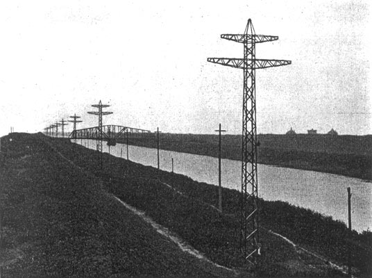
As will be gained from inspection of the accompanying illustrations, the poles are intended to accommodate two three-phase transmission circuits and a ground wire carried on the peaks of the poles which will extend the whole length of the line. The transmission voltage will be 44,000.
The erecting of the poles is shown in Figs. 1, 2 and 3. Some idea of their great size will be obtained from a glance at Fig. 4, where the height of the pole, almost 60 feet, may be compared with the man at the base.
The poles are of steel, square in plan section, of bridge construction, and weigh complete 4,000 pounds. On a side they measure 42 inches at the base and 20 inches at the top. The cross-arms are similarly of bridge construction, the lower arm being 18 feet long and weighing 600 pounds, while the top arm is 12 feet long and weighs 300 pounds. The material used in the diagonal braces is 2 by 2 by 3-16 inch angle. The size of the material in the corner posts varies from 3 1/3 by 3 1/2 by 1/4 inch at the base to 3 by 3 by 3-16 inch at the top of the pole. The rivets in the body of the pole are all three-quarters inch and in the cross-arms five-eighths inch.
Fig. 6 is a detail drawing of the pole construction, giving dimensions.
The Aermotor Company of Chicago, manufacturer of windmill machinery and towers, made the lowest bid for the construction of the poles and received $130 apiece for the 500 furnished.
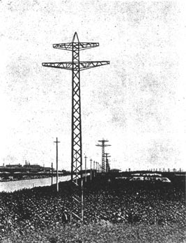
The poles are placed 350 feet apart. They are set into the ground 5 1/2 feet and the hole filled in with concrete which is brought up six inches above the surrounding earth and rounded off at the edges so that no water will lodge about the base. Fig. 5 shows a straight stretch of the line just out of Chicago and illustrates the accurate alignment which has been maintained in the setting. The view is typical of the upper end of the drainage canal and shows the water course itself and the high spoil banks flanking it on either side. The other poles shown in the picture are 40-foot telephone poles, which are, it may be seen, effectually dwarfed by the large steel structures.
Setting of the poles was undertaken by the Brennan Electric Construction Company of Chicago, which company also contracted for the wiring of the power house and the stringing of the high-tension wires. The bid made by this concern was much lower than others submitted, which is accounted for by the fact that the company had devised and figured on an economical method of construction which, while considered unique, has proved itself perfectly successful and equal to the various difficulties encountered.
The holes are dug perfectly square, are accurately lined, and are four feet on a side. This leaves three inches outside the pole on the four sides for the concrete into which the poles are set.
The derrick wagon seen in Fig. 2 was especially designed by the constructing company. It consists of a stone wagon with the platform extending one foot behind the rear axle; on this is set a 40-foot gin pole, to the top of which are attached guy lines which hold it in a perpendicular position. While setting a pole these lines are fastened to stakes driven in the clay or to bars inserted in the crevices in the rock. Moving from pole to pole the gin pole is kept in an upright position by the men who walk alongside and hold on to the guy lines.
In raising the steel poles (see Fig. 1) a three-quarter-inch wire cable is used, which is threaded through two 14-inch iron double-sheave blocks, then through the top of the pole over a sheave wheel, and finally down to the base of the gin pole on the derrick wagon, where it is attached to a crab hoist. Four men can raise the pole with this hoist. After the pole is set, lined and graded, it is securely guyed, and the derrick wagon proceeds to the next.
Concrete is placed in the following manner: A canal boat (shown in Fig. 3) loaded with stone and cement is towed up from the quarry and landed at the first pole to be concreted. On this boat is placed a Smith concrete mixer of one-half-yard capacity. The concrete is mixed on the boat and wheeled out and dumped around the pole. When the proper quantity has been placed about the pole the gangplanks are pulled aboard, the line untied and the boat floats down to the next pole.
| |||
| Fig. 4. View on Chicago Drainage Canal, Showing Lockport-Chicago Transmission Line. |
By this method one gang has set as many as 12 poles in a day, though difficulties are sometimes encountered which do not allow such progress. Three hundred and seventy-five of the poles are now set, beginning at the Chicago end, and the work of placing the balance and stringing the wires it is expected will be completed by October 15th.
| |||
| Fig. 5. View of Lockport-Chicago Transmission Line, With Sub-Station in the Distance. |
The poles were designed to carry the transmission wires on the lower arms 47 feet above the ground. The insulators of each three-phase circuit will be arranged at the apexes of an equilateral triangle six feet on a side, so that distance will be maintained between wires. The wires are carried 16 inches above the metal arms. The insulators, furnished by the Locke Insulator Manufacturing Company, are of the type shown in Fig. 7. They have a diameter of 14 inches and are 12 inches high, and were tested assembled ready for use at 120,000 volts. Each of the four shells tested at 60,000 volts before assembly. This insulater [sic] insulator, mounted on a suitable metal pin, is guaranteed for a maximum horizontal strain of 4,000 to 5,000 pounds and is ordinarily rated for 60,000 volts.
 |
| Fig. 7. Type of Insulator Used on Lockport-Chicago Transmission Line. |
At the top of the pole the four corner posts end in a cap which is fitted with a socketed clamp to be tightened down on the one-half-inch iron ground wire which will be carried the whole length of the line. This cable will connect all the poles electrically, and on account of its position above the transmission wires is expected to receive any lightning which may strike the line and carry it off to the excellent grounds afforded by the concrete imbedded poles.
 |
| Fig. 6. Detail Drawing of the Lockport-Chicago Transmission Pole. |
