[Trade Journal]
Publication: Western Electrician
Chicago, IL, United States
vol. 41, no. 2, col. 1-3
Hydro-electric Power Development
on the Muskegon River.
Although in a rather desolate spot, surrounded by sand hills and scrub oak, the site of the Croton Dam hydro-electric power plant now building by the Grand Rapids and Muskegon Power Company offers a scene of industry and activity. Already the Grand Rapids and Muskegon Power Company has in operation a waterpower plant at Rogers Dam on the Muskegon River, 51 miles north of Grand Rapids, Mich. Electrical energy generated at this plant is used for lighting and power in Grand Rapids, Muskegon, Holland and other towns intervening, besides supplying several street and interurban railways. Current is transmitted to Muskegon and Grand Rapids at 66,000 volts.
So great has been the demand for power that the company some time ago decided to build another plant of greater capacity about six miles down the river. Work is now nearing completion on the new dam and power house, known as Croton Dam. A feature of this enterprise is two steel-tower transmission lines, one to Muskegon and one to Grand Rapids, which will be operated at 100,000 volts. The line is being substantially constructed, each of the three legs of each tower being anchored with a special steel-concrete base made on the ground. Three 3,750-kilowatt transformers are now being installed in the Grand Rapids sub-station to receive the 100,000-volt current and reduce it to the distribution pressure.
In the accompanying group picture Fig. 1 shows the Rogers Dam project, now in full operation. Fig. 2 is a view of the up-stream side of the Croton Dam development during construction, while Fig. 3 shows the down-stream side.
The Croton Dam is built of concrete and steel, the power house housing the generators and' water-wheels being a part of the dam, much the same as the Sanitary District project at Lockport on the Chicago Drainage Canal. The working head of water at the dam is 41 feet, and to create this head a reservoir covering nearly 2,000 acres has been formed.
 |
| Fig. 1. Rogers Dam and Power House (Left) Fig. 2. Up-Stream Side of Plant at Croton Dam. (Right) Fig. 3. Down-Stream Side of Plant at Croton Dam Hydro-Electric Power Development on the Muskegon River. |
Provision has been made for the control of flood water by the installation of movable-crest sections, in the dam. These sections, shown at the right in Fig. 2, are raised or lowered by electric motors. Until the dam was completed, the river in its natural course flowed between the west end of the dam and the hill shown in Fig. 2. The river is shown in the foreground of Fig. 3, which, of course, is the opposite side of the power house at the left in Fig. 2.
The river channel at the side of the power house has now been closed, diverting the water into the reservoir. The work of changing the course of the river was accomplished largely by hydraulic excavating. Water at high pressure was forced through a large nozzle against the side of the hill, removing the dirt, which was washed down the hillside. At the bottom banks of trees and shrubs were thrown up, which served to check the progress of the hydraulically excavated dirt and form a new embankment.
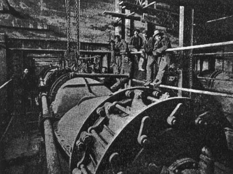
There are two generating units installed at Croton, each unit composed of a generator and eight waterwheels direct-connected. The waterwheels are of the Leffel type, each unit being guaranteed by the makers to deliver 7,200 horsepower at the generator shaft. One of the two group of eight wheels is shown in Fig. 4, the other group being located directly alongside. The wheels can be operated in sets of two, and the turbine chambers are divided into compartments so that any set of two wheels can be shut off if necessary.
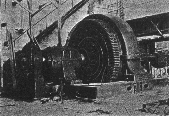
The generators, one of which is shown in Fig. 5, are Westinghouse three-phase 30-cycle machines. They will generate at 6,600 volts, which pressure will be raised to 100,000 volts for transmission. Three oil and water-cooled step-up transformers are installed for raising the voltage to 100,000.
The Croton Dam plant is attracting considerable attention among engineers, principally because it is one of the first to transmit at 100,000 volts. The older plant at Rogers Dam has already demonstrated the commercial practicability of generating electricity by waterpower and transmitting the power to points in Western Michigan. Besides supplying cities and street railways with light and power, many manufacturing industries are using the cheap power. A ready market awaits the output of the new plant.
J. B. Foote of Jackson, Mich., was in charge of electical engineering at Croton Dam, and W. G. Fargo of Jackson was the hydraulic engineer. Thomas Hume of Muskegon is president of the power company, and A. J. Bemus is general manager.
| |||
| Fig. 4. A Waterwheel Unit at Croton Dam Hydro-Electric Power Development on the Muskegon River (See Page 21). |
| |||
| Fig. 5. 3,000-Kilowatt Generator in Croton Dam Hydro-Electric Power Development on the Muskegon River (See Page 21). |