[Trade Journal]
Publication: Western Electrician
Chicago, IL, United States
vol. 43, no. 14, p. 241-244, col. 1-3
THE 110,000-VOLT TRANSMISSION INTO
GRAND RAPIDS, MICH.
Ten weeks of successful operation of the 110,000-volt transmission line into Grand Rapids, Mich., has fulfilled the predictions of high-tension authorities as to the practicability of such a working voltage and justified the courage of the local engineers in undertaking a transmission potential nearly twice that in any other locality in the world. For a year or more the 72,000-volt lines of the same Grand Rapids-Muskegon system had remained the highest operating voltage of authentic record, and so successful was the operation at this pressure that an even higher potential was decided upon for the new transmission line under construction from Croton Dam on the Muskegon River, to Grand Rapids. This was accordingly designed for 110,000 volts, and on July 16, 1908, it was put into actual service for the first time. Since then it has shown a gratifying steady performance.
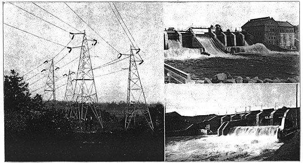
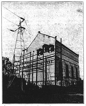
This 110,000-volt line, whose characteristic construction is shown in Fig 1, is 50 miles in length, extending from the Croton Dam on the Muskegon River (shown in Fig. 2) to the Wealthy Avenue sub-station at Grand Rapids. It forms a part of the 212 miles of transmission system of the Grand Rapids-Muskegon Power Company which utilizes the waterpower of the Muskegon and Grand rivers to furnish light and power for neighboring cities and interurban railways. The Rogers Dam water-power plant, on the Muskegon River, 18 miles north of the Croton Dam, is shown in Fig. 3.
| |||
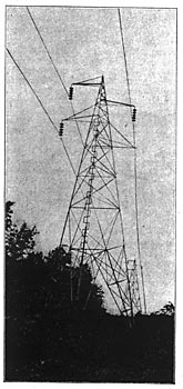
| (Left) Fig. 1 A Right-Angle Turn on the 110,000-Volt and 72,000-Volt Tower-Lines Near Grand Rapids. the 110,000-Volt Lines Are on the Right or Outer Side of the Turn (Right) Fig. 2. Croton Dam Power-Plant, Head of the 110,000-Volt Transmission Line Fig. 3. Spillway at Rogers Dam Power Plant, the Head of the 72,000-Volt Transmission System High-Tension Transmission Lines and Generating Station of the Grand Rapids-Muskegon (Mich.) Power Company. |
At Croton Dam two 7,000-horsepower hydraulic turbine-generator sets utilize the head of 41 feet, generating 30-cycle current at 7,200 volts. This is stepped up through three 3,750-kilowatt transformers to 110,000 volts and transmitted over the steel-tower line to Grand Rapids, where a similar set of transformers receives it, lowering the potential to the sub-station bus-bar voltage of 7,200 as well as supplying a 20,000-volt transmission line to an interurban sub-station.
CROTON DAM DEVELOPMENT
Referring to the accompanying map of the Grand Rapids-Muskegon Power Company's transmission system (Fig. 4), the Croton Dam on the Muskegon River is near the junction with the Little Muskegon and seven miles from the railroad station of Newaygo. Construction work was begun in June, 1906, and as a foundation 3,000 oak piles and two rows of heavy interlocking steel sheet piling 30 to 36 feet in length were sunk below the river bed. The dam and power house are of reinforced concrete construction, the wheelhouse forming a part of the buttress. The concrete core wall of the dam is 300 feet in length and 42 feet high, set upon a foundation of steel piling. Two hundred feet down the stream from the flood gates there extends an apron of reinforced concrete from four to two feet in thickness.
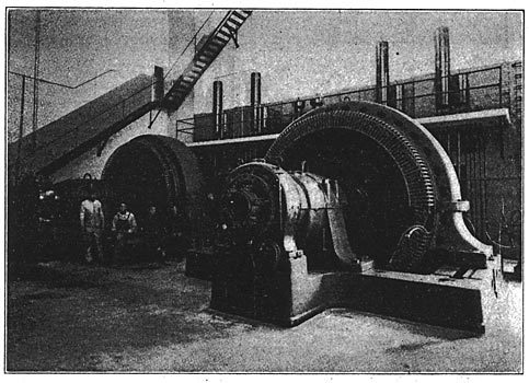
The working head of the development is 41 feet and is maintained by eight steel tainter flood gates, each 13 feet by 20 feet, and a bear-trap or movable-crest dam 40 feet long. The power house has a floor area 75 by 125 feet and is 60 feet high. Reinforced concrete walls protect it from back-water, and the wheel section is of concrete construction for the lower 40 feet. Two sets of eight 45-inch Samson waterwheels mounted on. horizontal 12-inch by no-foot steel shafts drive the two 7,000-horsepower Westinghouse three-phase generators at 225 revolutions per minute, supplying 30-cycle current at 7,200 volts. These two generators with their exciters are shown in the interior view of the Croton Dam power house, Fig. 6.
At the site of the dam the river valley is about 600 feet wide, with banks 40 and 120 feet high, respectively. The waste-gate section of the dam is 238 feet long and its outer end adjoins the power house, which, with the turbine room, is 160 feet long. A fill embankment completes the remaining 200 feet of the dam across the valley. The dam required 30,000 barrels of cement and 1,250 tons of steel in its construction and impounds the waters of the Muskegon River to form a pond nine miles long and covering 1,600 acres. In the accompanying down-stream view of the Croton development, Fig. 2, the tainter gateways are seen in the left of the picture flanking the wider bear-trap. The brick building is the power house containing the generators, and at the right is the wheelhouse, each of the four tail-race tunnels taking water from two wheels on each of the generator shafts.
The tainter waste gates at the Croton and Rogers dams are of interest, as they were of special design. The gates are separated by massive concrete piers, and each closure swings on two bearings, six-inch cold-rolled steel pins imbedded in the piers. As the gates are well trussed there is no central bearing or through shaft needed. Each gate is fitted with a heavy oak block seating on a wooden sill carried on a 15-inch channel-iron imbedded in the concrete. The joints are made watertight by attaching five-inch strips of three-ply rubber belting on the up-stream face of the gate so that the pressure of the water makes a watertight joint. The gates are controlled by motor-driven hoisting crabs. The movable crest section has a vertical travel of 3 1/2 feet and is operated by two motor-driven hoists.
On the down-stream side of the generator room are placed the three 3,750-kilowatt step-up transformers. These are water-cooled and oil-insulated and serve to step-up the generator voltage of 7,200 to the transmission potential of 110,000 volts. The frame and "rows of strain insulators effecting the power-hcuse entry are to be seen upon close examination of the Croton Dam exterior view, Fig. 2.
110,000-VOLT TRANSMISSION LINE
The 110,000-volt transmission line from Croton to Grand Rapids is the highest operating voltage in the world, as before remarked. For several years a California power company has enjoyed the reputation of operating at 80,000 volts, for which potential its lines were designed, but its engineers are understood to admit that the highest voltage ever actually worked has been 57,000 volts. A number of other lines are in operation, of course, at voltages in the neighborhood of 60,000.
The 110,000-volt line of the Grand Rapids-Muskegon Power Company is 50 miles in length. The wires are carried by Hewlett suspension-type, five-part insulators on large tripod steel towers having a tetrahedral form of bracing. These towers are 53 feet in height and spaced 500 feet apart on the straight course. Their bases are cemented into concrete anchors buried in the ground.
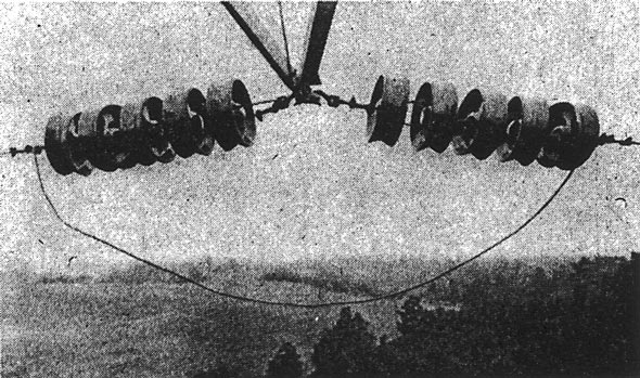
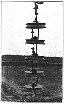
A stranded conductor with a hemp center and having a carrying capacity equivalent to No. 2 wire is used. The suspension and strain five-part insulators, with the method of attaching to the wire, are well shown in detail in Figs. 5 and 10. Each porcelain disk is 10 inches in diameter and is tested to 95,000 volts, so that the total break-down voltage of the series is almost half a million volts, giving a factor of safety of nearly five. This is a valuable feature of the suspension insulator, since in the case of one or even several of the disks being broken the remaining insulators in the set enable the line to continue operation without interruption.
 |
| Fig. 4. Map Showing Transmission Lines and Stations of Grand Rapids-Muskegon Power Company. |
The photograph from which Fig. 1 was taken shows an interesting right-angle turn made by the use of the strain insulators on the 110,000-volt and the 72,000-volt lines near the city of Grand Rapids. Here the 72,000-volt pole line has been changed to the steel-tower construction for a short distance out of the city sub-station. The 110,000-volt wires are on the right or outer side of the turn shown in the picture. Fig. 9 shows a characteristic straight section of the line using the suspension type of insulators.
A 50-mile transmission line operating at the enormous potential of 110,000 volts presents some interesting and unusual electrical phenomena. Owing to the static discharge at this potential a continual noise or buzz is heard in the neighborhood of the high-tension line. This 30-cycle note can be heard distinctly at a distance of a hundred feet from the lines and is very noticeable compared with the silence of the 72,000-volt line near by.
| |||
| Fig. 5. 110,000-Volt Strain Insulator |
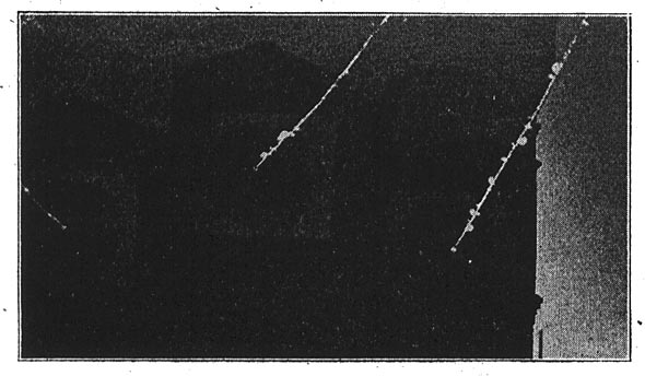
In the dark the 110,000-volt wires appear luminous with a brush discharge distributed over their entire length. This luminescence is about of the quality of a rubbed phosphorous match, though at places where dust or some irregularity forms a discharge point a more brilliant brush display is produced. A night photograph of this 110,000-volt line was given on page 150 of the Western Electrician of August 29th, and Fig. 12 herewith is a reproduction of a two-hour exposure of the lines entering the Wealthy Avenue sub-station. Some idea of the scale of the picture is afforded by the distance between the wires, eight feet. The barbs of light due to localized brush discharges are well shown.
| |||
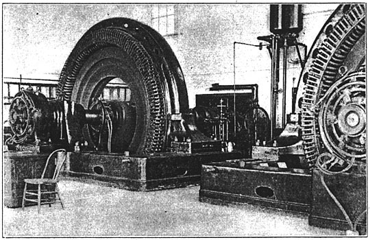
| Fig. 6. 3,600 Kilowatt Generators at Croton Dam Interior Views of Grand Rapids-Muskegon Company's Hydro-Electric Power Stations |
While 110,000 volts is the sustained line potential, even this value is often, exceeded, for a range of a few thousand volts on the line is comparatively close regulation. At night the voltage is often held at 120,000 to 125,000 volts for the benefit of some 120-volt lamps on the system. With a slight swing of the voltmetay needle the brush discharge changes visibly, increasing in brightness out of proportion to the voltage change.
| |||
| Fig. 7. Generators at Rogers Dam Power Plant Interior Views of Grand Rapids-Muskegon Company's Hydro-Electric Power Stations |
Ordinary effects of capacity arid the line characteristics are greatly exaggerated in a line of such effective insulation and operating at this extremely high voltage. For instance, a slight wind blowing across the disconnected line serves to charge it to a very high potential. Whether from frictional electricity developed by the motion or from the drifting of charged masses of air or clouds against the line, sparks an inch in length may often be drawn. This was a troublesome cause during the construction of the system, as the linemen continually received slight shocks from the open line unless the wires were tied together and grounded. In view of the, present difference of opinion in relation to lightning protection the fact is worthy of note that the 110,000-volt line is provided with neither lightning arresters nor a ground wire.
There are no operating switches in the 110,000-volt circuit, the high-tension windings of the two sets of transformers 50 miles apart being permanently tied together. The operation of this line without lightning arresters or ground wires has so far provided a record very encouraging to those who do not admit all the advantages of such protection. To date the 110,000-volt line has given less trouble, it may at least be said, than the 72,000-volt circuit which is provided with both arresters and a ground wire throughout it's length; and the new line has already successfully weathered one of the most severe, storms that ever visited the Grand Rapids region.
At the Croton power house the 7,200-volt primary circuits of the 110,000-volt transformers are controlled by Westinghouse 300-ampere type E oil circuit-breakers. With no further switching connection in the transmission circuit the three 3,750-kilowatt transformers at the Wealthy Avenue substation supply a 20,000-volt transmission line to the sub-station of the Grand Rapids, Holland and Chicago Electric Railway as well as the 7,200-volt station bus-bars connected to the downtown Grand Rapids sub-station. These enormous 110,000-volt transformers are shown in the interior view of the Wealthy Avenue sub-station. Fig. 8. A comparison of their gross dimensions with the chair in the photograph will furnish an estimate of their great size. They measure approximately 19 feet in height and 15 feet in diameter. The 110,000-volt primary terminals, which are plainly shown in the photograph, are connected in delta to the wires of the transmission line and carried overhead into the building. The oil switches which handle the 20,000-volt and 7,200-volt circuits are motor controlled and in accordance with modern practice are indicated on the switchboard by lamps.
As a matter of test, when the 110,000-volt line was finished building, but before connecting to the transformers at Croton, the dead-ended line was energized from Grand Rapids and the reversed readings of the station watt-hour meter taken. As an average of 52 hours a value of 152 kilowatts an hour was obtained, representing the total leakage and charging losses of the line and the exciting and other losses of the one set of transformers.
72,000-VOLT SYSTEM
The Wealthy Avenue sub-station, located across Grand River and a mile from the business center of Grand Rapids, also receives the 72,000-volt line originating at the Rogers Dam power house on the Muskegon River. The entrance, of this line is shown at the left of the 110,000-volt wires entering the sub-station, in Fig. 11, and the 72,000-volt transformers may be seen at the right in the station interior, Fig. 8. Special 72,000-volt oil switches, designed by Mr. J. B. Foote, electrical engineer of the company, are inserted between the line and the transformer primaries, and type E 7,200-volt switches control the primary supply to the bus-bars, which are also energized from the secondaries of the 110,000-volt transformers. The 7,200-volt station voltage is transmitted to the downtown Grand Rapids sub-station at the corner of Fulton and Ellsworth streets, where it is made available for local distribution through rotary converters and frequency changers.
| |||
| Fig. 8. on the Left Are the 110,000-Volt Transformers, Stepping Down to 20,000 Volts and 7,200 Volts. 72,000-Volt Transformers Are Seen at the Right Interior View of Wealthy Avenue Sub-Station Grand Rapids |
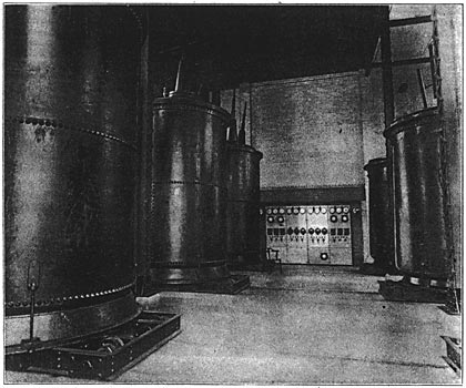
Both sets of transformers in the Wealthy Avenue sub-station are mounted on trucks movable on transverse tracks so that any transformer may be run out into the middle passage under the travel of an electric crane of sufficient capacity to handle any part of the apparatus.
Referring to the map (Fig. 4), it may be explained that the 72,000-volt line into Grand Rapids is controlled from the Casnovia switch house which is the branch point for another 72,000-volt line to Muskegon, 26 miles west. The main 72,000-volt line passes the Croton station intact, leading directly to the Rogers Dam generating station.
The 72,000-volt line is carried on 14-inch four-part Locke insulators mounted on cedar and cypress poles, 40 to 60 feet in height, and placed 40 to the mile. Eighteen-inch wooden pins are used on fangents, and for curves galvanized steel-tube pins have a lead thread cast on the head to carry the insulator. The line conductor is of No. 2 medium hard-drawn copper. On one end of the five-foot upper cross-arm a ground wire of No. 6 galvanized iron is carried and grounded every fifth pole. The line is located on a-private right-of-way four rods wide.
ROGERS DAM POWER PLANT
The interior view of the Rogers Dam power house. Fig. 7, shows the two 1,500-kilowatt Westinghouse alternators generating 30-cycle current at 7,200 volts. Three 1,250-kilowatt, single-phase, 10-to-1 step-up transformers, arranged in delta, deliver this to the line at 72,000 Volts. The city of Big Rapids, a short distance away, is supplied with power at the generator voltage, 7,200. The 72,000-volt transformers, together with their 72,000-volt, hand-operated oil switches, are placed in a separate building 50 feet from the power house.
The Rogers Dam plant operates at a head of 39 feet, which is utilized by two pairs of horizontal center-discharge Samson turbines in open steel-plate penstocks. The turbines are direct connected to the generators and controlled by Lombard governors. As at Croton, the exciters are mounted on the main shafts.
The Rogers Dam structure is foundationed on a line of steel piling driven into hard pan, and on which a 10-inch concrete core wall is reinforced. The waste-gate section has an over-all length of 150 feet and contains six tainter gates 20 feet by 12 feet flanking a six-foot log sluice. The gates are raised by one of two hoisting crabs which travel on a 24-inch gauge track and contain four-horsepower motors geared to winding drums. The crabs can exert an 8,000-pound pull, and in case of such an emergency as the breakdown of both motors or the lack of current, may be hand operated. Down-stream from the gates is a tumble bay formed by an overflow weir. The retaining walls are extended 240 feet, forming a wasteway channel 180 feet wide.
| |||
| Fig. 9. 110,000-Volt Transmission Line, From Croton Dam to Grand Rapids, Showing Suspension Insulators |
Other lines of the Grand Rapids-Muskegon Power Company's system are the feeder transmission lines supplying the sub-stations of the Grand Rapids, Grand Haven and Muskegon Electric Railway with 17,000-volt current and the Grand Rapids, Holland and Chicago interurban road with 20,000 volts. At the Jenison power house on the latter line there is steam equipment driving two 750-kilowatt Westinghouse alternators also generating 30-cycle current. The Fruitport power house on the line of the Muskegon railway contains three 250-kilowatt double-current generators furnishing 650-volt direct current and 300-volt alternating current, and two 250-kilowatt, 650-volt, direct-current generators. In the Grand Rapids sub-station is a 500-kilowatt Curtis turbo-generator designed to operate at the system frequency of 30 cycles. Other older steam reciprocating auxiliary equipment located here may be impressed into service in case of line breakdown or low water.
A PIONEER HIGH-TENSION LINE
The transmission line now operating at 13,500 volts frtm Lowell to Grand Rapids was Michigan's first long-distance transmission of waterpower. The hydraulic development was begun in 1890 at Lowell on the Flat River, a tributary to the Grand, by the Peninsular Light, Heat and Power company, which after several changes in control is now owned by the present Grand Rapids-Muskegon Power Company. The dam had a 12-foot head and a wheel capacity of 300 horsepower, a 180-kilowatt, 60-cycle alternator generated at 1,000 volts, and this was transformed to the transmission potential of 10,000 volts. The transmission at this pressure, 18 miles to Grand Rapids, was considered a wonderful achievement, although the pioneer high-tension constructors had to-remove sqme prejudices before the public, and especially the public-governing bodies of that day, could be made to see the feasibilty of transmitting current for power over such a distance.
| |||
| Fig. 10. 110,000-Volt Suspension Insulator |
In 1903 the second dam on Flat. River was built, giving a head of 30 feet and creating a 700-acre pond. This dam is 480 feet in length and has a waste-gate section 200 feet wide. Two 23-inch Samson turbines are direct-connected to 300-kilowatt, 13,500-volt, 30-cycle, three-phase generators, which are connected directly to the transmission line into Grand Rapids.
A small waterwheel in a canal diverted from the Grand River near the city of Grand Rapids, owned by the company, also develops enough power to make its operation of some slight service when the river flow is in excess of that required by other mill waterpower plants along the river.
INDUSTRIAL USE OF POWER
Having thus shown itself a leader in methods of power development and transmission the Grand Rapids-Muskegon Power Company has made an equally aggressive and effective business campaign, with the result that the territory it supplies is most modernly equipped with household and business electrical service and electrical factory operation.
| |||
| Grand Rapids Terminus of the 110,000-Volt and 72,000-Volt Transmission Lines Fig. 11. Wealthy Avenue Sub-Station |
The plant of the Grand Rapids Plaster Company, one of the largest manufacturers of plaster products, is driven entirely by electric power purchased from the Grand Rapids-Muskegon Power Company. A total of 235 horsepower in 440-volt, 30-cycle induction motors has been installed. The gypsum is hauled from the mines by a windlass operated by a 20-horsepower motor and dumped into a hopper leading to a crusher driven by a 30-horsepower motor. Motor-driven conveyors transfer the crusher product to six mills, each operated by a 20-horsepower motor. The material is elevated, screened and fanned and finally conveyed to large kettles, where it is baked to drive out the moisture. These kettles, each having a capacity of 12 tons, are kept stirred by large paddles driven by a 40-horsepower induction motor. The installation is modern, circuit-breakers are used throughout, and the wiring is enclosed in steel conduit.
| |||
| Showing Luminous Discharge and Brush Displays. the Wires Are Eight Feet Apart Fig. 12. 110,000-Volt Sub-Station Entry at Night |
The Grand Rapids Hand Screw Company has a connected load of 210 horsepower of induction motors. These motors are largely direct-connected to the planers, lathes, saws, sanders, shapers and cut-offs. Meters are installed in each department and the central-station service has brought out the following advantages over steam or isolated-plant power: Simplicity, economy of space, low initial cost, low operating cost and superiority in compiling records of power cost and production. The Fox Typewriter and Machine Company of Grand Rapids has a connected load of 190 horsepower in motors.
The new Muskegon factory of the Brunswick-Balke-Collender Company, manufacturer of billiard and bowling-alley equipment and other game devices, has a connected load of 1,250 horsepower in induction motors driving the many interesting automatic and semi-automatic machines used in the manufacture of its products. The Amazon textile and knitting mill at Muskegon is also operated from the power company's lines.
ELECTRIC HEATING
A novelty in the way of hotel heating by electric radiators was introduced by the active solicitors of the power company a short time ago. The second floor of the Eagle Hotel, one of the oldest and best known in Grand Rapids, was equipped with electric radiators as, an alternative to installing an expensive steam-heating system. As a result cheerful electrical heat is instantly available when required, and the guests seem delighted with the innovation. The cost is quite low, since the consumption of current continues only during actual use, and of course with waterpower generation the company is enabled to make favorable rates. Three heater units, each measuring 10 inches long by 3 inches in diameter, consuming 750 to 1,000 watts, are arranged for connection to plugs in each room. The hotel is further equipped with automatic electric switches on the doors of the refrigerator room controlling lights inside, metallic-filament lamps throughout, etc.
An unusually large number of electric flatirons and other heating specialties have been installed by the company.
SPECIAL LIGHTING FEATURES
The accompanying night photograph. Fig. 13, shows the series tungsten lamp illumination on Canal Street, Grand Rapids, for which current is supplied by the power company. The installation consists of 15 spans of 18 pendent, 60-candlepower, 75-watt tungsten lamps in series on each span, the drops arranged in length to form graceful arches. The spans are 110 feet in width and 100 feet apart and cost for material and labor $50 each, or $750 in all. The Merchants' Association had the work put up so that the individual shares of cost were slight. The installation is permanent. The power company furnished the lamps and takes care of renewal and maintenance.
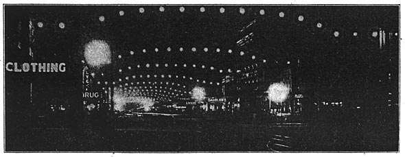 |
| Grand Rapids Terminus of the 110,000-Volt and 72,000-Volt Transmission Lines Fig. 13. Series Tungsten Illumination of Canal Street, Grand Rapids |
Grand Rapids has an unusual number of electric signs for a city of its size. With a population of 110,000 the Grand Rapids lines of the power company have a sign lamp for every five inhabitants. A record for new-business getting of 30 signs in 30 days was recently established.
THE SHOW ROOM
The domestic use of electricity for illumination and heating has received a great deal of attention from the company, which maintains a handsomely appointed show room in connection with its business office at 47 Monroe Street, Grand Rapids. Handsome domes, shaded lamps, electroliers and other attractive lighting fixtures invite the passerby to a more extended inspection of the electric radiators, stoves, coffee percolators, chafing dishes, egg boilers, flatirons, hot-water bottles, heating pads, cigar lighters, etc. The business office of the Grand Rapids district occupies part of the lower floor and the second story is taken up with executive and general offices. The headquarters of the supervision and maintenance departments are in a concrete building newly erected by the company at Fulton Street and Ellsworth Avenue. This also contains the supply stores and Grand Rapids storage battery and is adjacent to the downtown sub- station and power house.
PERSONNEL
The officers of the Grand Rapids-Muskegon Power Company are: President, Thomas Hume; vice-presidents, W. A. Foote, David D. Erwin; secretary, George L. Erwin; treasurer, J. G. Emery, Jr. H. W. Hillman is sales manager, J. B. Foote, the electrical engineer; W. G. Fargo, hydraulic engineer; A. F. Walker, general superintendent, and F. E. Greenman, assistant general superintendent.
