[Trade Journal]
Publication: Engineering News
New York, NY, United States
vol. 44, no. 24, p. 398-404, col. 1-3
THE SNOQUALMIE FALLS WATER-POWER PLANT AND TRANSMISSION SYSTEM.
(With two-page plate.)
Within the past few years a number of plants have been established on the Pacific slope to utilize natural water powers for generating electricity to be transmitted to distant points and there used for lighting and power purposes. Among the most interesting and important of these plants is that at the Snoqualmie Fails in Washington. For this plant, no long flume for pipe line is required to develop the necessary head of water, as the Snoqualmie River has at the Falls a vertical drop of 270 ft., giving an available energy of 30,000 to 100,000 Hp. In this respect the plant resembles that at Niagara Falls where the vertical drop is 153 ft. and the total power produced with the available head of is 145 ft. is over 3,000,000 HP., of which 50,000 HP. are utilized by the present plant. In the placing of the electrical machinery, however, there is an essential difference, for while the Niagara Fails plant has this placed in a building above ground, the Snoqualmie Falls plant has the water wheels and electrical machinery all installed together in a large underground chamber, whose floor is directly above the tail race tunnel which extends to the river below the Falls. The force of the water is used to drive impulse wheels on horizontal shafts instead of turbines on vertical shafts, as at Niagara Fails. Another notable feature of the plant is the use of aluminum wire for the long-distance transmission lines. The entire plant represents an investment of about $1,000,000.
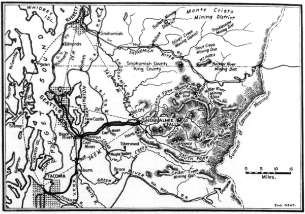 |
| Fig. 1Map of the Location of the Snoqualmie Falls Power Plant and Transmission Lines. |
The waterfall and the land on either side were purchased in the autumn of 1897 by Mr. Wm. T. Baker, of Chicago, who organized the Snoqualmie Falls Power CO. early in 1898. Of this company, Mr. Charles H. Baker is President and General Manager, and the other officers are as follows: Vice-President, A. H. Andrews; Secretary and Treasurer, George Lyon; Manager at Tacoma, James C. Drake. The company has its main offices at Seattle, Wash., and a branch office at Tacoma, Wash. Mr. Thomas T. Johnston. Consulting Engineer of the Chicago Drainage Canal, was Consulting Engineer during the construction of the works, and Mr. James J. Reynolds was Superintendent of Construction. The Electrical Engineer was Mr. E M. Tingley, and Mr. Robert McF. Doble was Mechanical Engineer. The construction work was done by the company and not by contract. We are indebted particularly to the President, Mr. Charles H. Baker, for information. drawings, photographs, etc., made we of in this article.
HYDRAULIC AND METEOROLOGICAL CONDITIONS.
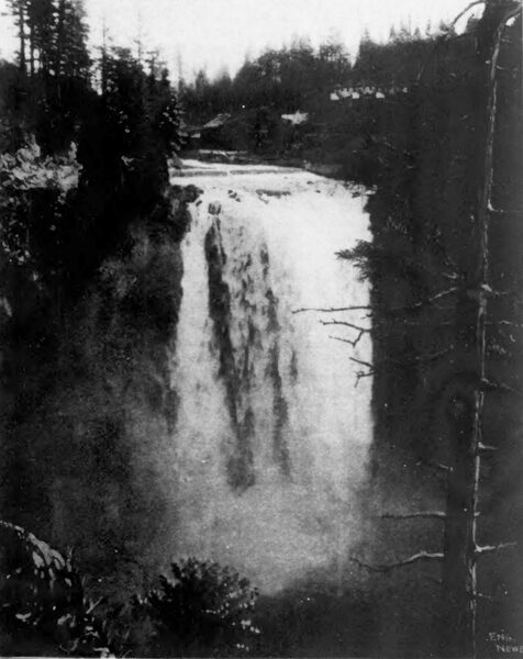
The great fall of the Snoqualmie River is about 34.5 miles northeast from Tacoma (in a straight line), 34-1/2 miles southeast from Everett and 25 miles west from Seattle, being situated in the foothills of the Cascade range. The general location is shown by the map, Fig. I, and in Fig. 2 is given a view of the fall. The river proper commences about three miles above the fall, at the junction of three forks which flow westward down the slopes of the range. Below the Falls the river runs almost due north until it makes a junction with the Skykomish River, the two forming the Snohomish River, which flows into Puget Sound near the city of Everett. The summit of the fall is about 600 ft. above sea level, while the watershed reaches elevations of 8,000 ft. above this level. The area of the watershed is about 500 sq. miles, and extends above the snow line so that the river has a large low water flow in the dry season of August and September. The rainfall, or rather the total precipitation, at the Falls is about 90 ins. per annum, while in the country along the shores of Puget Sound the rainfall averages but about 37 ins. The meteorological reports show that the precipitation over the watershed increases as the crest of the range is approached, reaching 150 inches and over. The flow of the river is about 1,000 cu. ft. per sec at its lowest stage, increasing to over 10,000 cu. ft. per second at its flood periods.
| |||
| Fig. 2.View of Fall. |
At an early stage in the enterprise the company placed in the field a party to determine the hydrographic, meteorological and other features the watershed, as well as its geological and geo graphical conditions. One peculiar physical characteristic which was discovered was that some of the streams tributary to the three forks disappear underground occasionally, and reappear again at a distance of about half a mile. By the construction of dams or dikes, some of the large likes on the watershed can be utilized as impounding reservoirs, so as to ensure a uniform flow sufficient to develop nearly 100,000 HP throughout the year, should a demand for so much power eventually be found. It has also been r determined that by the erection of a 59 ft. dam above the headworks a reservoir could be formed having an area of 15 sq. miles, and an average depth of 25 ft. This would almost double the power, should the growth of the industries served make this desirable in the future.
The rock at the Falls is basaltic, with no regular cleavage. It is hard and non-absorbent, and is apparently divided by seams into great ledges. These conditions led to the adoption of the plan of placing the machinery in an underground chamber, as already noted. It was at one time proposed to build a power house near the base of the Falls, but this would have been at a disadvantage on account of the clouds of spray which keep everything damp, and coat all of the surroundings with ice in cold weather.
As a part of the preliminary steps of the enterprise, a topographical survey was made of land within 1/4-mile radius from the Falls, including soundings of the river bottom. Gages were set at intervals above and below the Falls, to show the varying elevation of the river, and these gages have been read three times daily during the past three years. Daily records of rainfall, barometer, temperature, and weather conditions are kept by the company at Snoqualmie Fails, Issaquah and Renton, and are reported to the office of the U. S. Weather Bureau at Seattle. The water of the river is usually pure and clear, but occasionally carries some white clay in solution, as well as slit after the freshets. These occur generally in November, owing to the heavy rainfall, and in June, owing to the melting snows. The water level varies between the high and low stages throughout the year, with occasional freshets at different times, but the main floods precede the dry season very closely, so that storage for an increased flow would not have to be maintained for any considerable time. The river does not freeze during the winter, and there is neither floating ice nor anchor ice to be dealt with. At a point about above the Falls, where a uniform cross-section of the river was obtained, the company established a station for measuring the velocity of flow at all stages, an exhaustive series of experiments being made with a current meter. The average velocity is about 10 ft. per second. The law governing the flow of the river is found to be represented by a parabolic curve with the following equation, in which X is the discharge in cu. Ft. per second, and Y is the elevation of the water line:
X = ((Y**2 106.8 x Y + 2,851.6)/0.1))
HEADWORKS.
A plan of the headworks above the Falls is shown in Fig. 3, and this also shows the position of the underground power chamber and the tail race tunnel. The intake bay is a rectangular chamber, about 60 ft. long (parallel with the river) and 20 ft. wide. It has walls and a center pier of concrete masonry 6 ft. thick and 25 ft. high, built upon the solid rock formation, its floor being on a submerged reef and about 5 ft. above the river bed. This bay is protected from the river by a timber grating across the opening, supported by a steel girder construction, bearing against the walls and pier. The timbers are 12 x 12 ins., laid horizontally with 12-in. spaces between them, through which the water flows into the intake. This grating protects the works from floating trees and logs, while just inside the intake are inclined steel screens made of flat bars on edge, which serve to exclude the smaller debris. The intake has two head bays, separated by the pier, having been built for twice the capacity of the present power development. The idle head-bay now affords a place for a water rheostat, capable of taking 2,500 electrical HP. This rheostat is connected with the switchboard in the machinery chamber and is held in reserve for emergency use should the normal load be suddenly taken off.
A rudder boom 300 ft. long is moored above the intake and extends beyond it. By turning the capstan at the head of the boom, the rudders are thrown out and cause the boom to swing out into midstream, so that it serves as a fender to deflect floating logs, etc., from the intake. The river is 150 ft. wide from the head-bay to the opposite shore, and about 15 ft. deep at ordinary stages. The face of the intake was continued 400 ft. up and 200 ft. down stream in the shape of heavy retaining walls built of sawed cedar timber, tarred. The space behind them is filled with excavated rock, and has a top dressing of soil for a lawn and shrubbery.
At the end of the lower bulkhead, a submerged concrete dam is built across the river, resting on the rock bottom, and this raises the low water elevation of the river 6 ft. at the intake. This dam whose location is shown on the plan, Fig. 3, is the form shown by the elevation and section. Fig. 4. It was first framed of heavy timbers sheeted over with 6-in. planking, and then filled in solid with concrete. It was built about the time low water flow, portions of the river bed being laid bare by cofferdams. Preparatory to the construction of the dam, the river bed was thoroughly cleaned of loose rock, and was roughened by occasional blasts so as to afford a good footing. In addition to this, pieces of steel rail were driven in holes drilled 2 ft. deep, the rails extending up into the concrete body of the dam. Old railway cables were also embedded in the concrete to perfect the bond. The dam has a batter of 2 on 1 up stream and 1/2 on 1 downstream, with a level crest 8 ft. wide. At each end of the dam is an abutment pier of concrete 8 ft. square, these being 210 ft. apart. The dam was built on a natural rock ledge, some 3 ft. above the river bottom. It is always submerged from 2 to 10 ft. according to the stage of the river, but at extreme low water (when the plant shall have been enlarged) it will be possible to construct a bear-trap dam between these piers. This will afford storage to equalize the daily flow, as the water will be backed up in the main river two miles and also in extensive tributary lakes. The dam varies in height from 3 to 10 ft., and in width on bed rock from 16 to 35 ft., according to the conformation of the river bottom. The lower bulkhead is only 5 ft. higher than the dam, so that flood waters have a very considerably increased sectional area of discharge, as shown by the plan. The capacity of this spillway is such as to insure the complete discharge of an extreme flood without the river backing up to an unusual elevation. The top of the upper bulkhead is above flood level.
About 27 acres of ground covering the works. the brink of the Falls and both banks of the river have been laid out as a park, with lawns, walks and flower beds, the grounds being illuminated by arc lamps. Comfortable cottages and a dormitory. with all modern conveniences, have been erected by the company, and there is also a cottage for the executive officers and fur visitors.
SHAFT, CHAMBER AND TAIL-RACE TUNNEL.
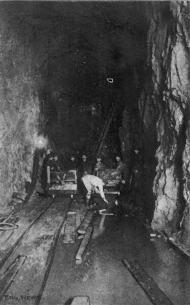
The general arrangement of the plant, with its underground power chamber, is shown in Fig. 5. About 300 ft. above the Falls, a shaft 10 x 27 ft. was sunk in the bed of the river on the south side, descending 270 ft. to the level of the river below the Falls. While this shaft was being excavated, a tunnel 12 ft. wide and 24 ft. high, with a fail of 2 ft. in its entire length, was drifted in from the face of the ledge below the Falls, to an intersection with the bottom of the shaft, a distance of 650 ft. Fig. 6 is a view taken during the construction of this tail race tunnel. Beginning at the foot of the shaft and extending over and along the tunnel, a chamber 200 ft. in length, 40 ft. wide and 30 ft. high, with the floor at the elevation of high water below the Falls, was excavated out of the solid rock. This chamber forms the power-house or machinery room in which the water wheels and electric generators have been installed. At average stages of the river the water is about 12 ft. deep in the tunnel, while during flood seasons it nearly fills the tunnel. The tunnel extends under the floor of the chamber, forming a tail race with a concrete roof 5 ft. thick. The walls of the chamber have been left rough and white-washed, while the floor is covered with concrete. About 700 incandescent lamps are used to light the shaft, chamber and tunnel. The chamber is ventilated by natural draft through the tail race and up the shaft, the draft being so strung that it has to be curbed. The chamber is said to be cool and perfectly dry, the temperature remaining the same (about 55 F.) throughout the year. This low and uniform temperature contributes to high efficiency of the generators.
| |||
| Fig. 6.Excavation of Tail Race. |
Work was commenced as soon as the organization of the company had been perfected. The construction plant included two 125-HP. boilers an Ingersoll-Sergeant air compressor delivering air at 100 lbs. pressure into a receiver 4-1/2 ft. diameter and 12 ft. high, 10 rock drills working under 6 lbs. pressure, and a sinking pump with 5-in. suction and 4-in. discharge to keep the shaft excavation dry. Owing to the solid character of the rock however, very little water entered the excavation. It was surrounded by a cofferdam 15 ft. high to prevent flooding in case of high water in the river. Over the shaft was a hoisting trestle 50 ft. high for the cages, which were operated by a 75-HP. double friction-drum engine, which could raise a load of 6,500 lbs. at a speed of 450 ft. per minute. The rock dumped at the trestle was carried by a gravity tramway to a Gates crusher with a capacity of 70 cu. yds. This was driven by a 15-HP. engine, and crushed stone was piled up for future use in the concrete work. All the concrete was mixed by hand.
To supply air to the drills in the tunnel, a pipe line was extended 400 ft. to the edge of the cliff, and a section of pipe lowered to the bottom, a depth of nearly 300 ft. Two men suspended by ropes, and working in the whirling spray and wind of the chasm, put the pipe lengths together, building it up from the bottom and constructing the necessary timbering to support it against the rough face of the cliff. At first all tools and material had to lie carried up and down a winding stairway, but a standing cable was soon put in place, on which ran a box for top's, operated by means of a windlass. All machinery and supplies were delivered by the Seattle International Ry., which runs close to the works, as shown in Fig. 3. For handling heavy material, a trestle was built over the sidetrack and extending to the shaft; upon this was a traversing hoist, by which the material was raised from the cars and carried to the works. The first drill was set in operation On April 17, 1898, and the work was then prosecuted by day and night until its completion.
HYDRAULIC PLANT.
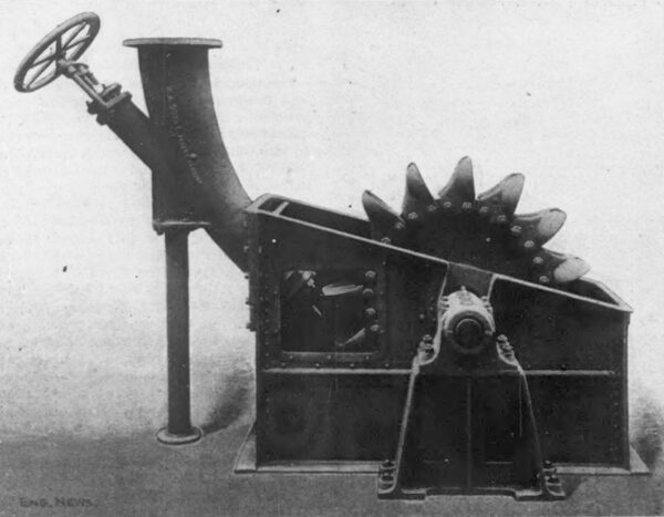
Each Intake bay contains a massive head gate moving vertically, which controls the flow of water through an opening 8 x 12 ft., through the shore wail into the penstock. The gate is raised and lowered by mechanism connected with the piston rod of a hydraulic cylinder. The shaft is 8 x 27 ft. and at the top has three compartments; the two end compartments are for the penstocks, while the center one, enclosed at the top by a steel bulkhead, forms a shaft 8 x 10 ft. for the hydraulic elevator and the main cables forming the outgoing conductors, and also for raising and lowering machinery, etc. The steel bulkhead which encloses this center shaft extends from the bottom of the intake hay to the surface of the ground. It is built up of steel plates, and is stiffened by horizontal frames of I-beams on the outside, riveted to the plates and to each other at the ends. Below it, the elevator shaft is timbered and sheathed with plank. At the surface, this shaft is surmounted by a small building. The penstock already built is a steel pipe 7-1/2 ft. diameter, passing through a concrete roof which keeps the shaft watertight. The plates are in 8-ft. courses, and are 1 in. thick for the lower half of the pipe; in the upper half, the thickness decreases from 7/8-in. to 1/2-In. at the top. The Joints are heavily riveted, and calked watertight. At a depth of 250 ft., the penstock reaches the chamber and connects with a horizontal cylindrical receiver which rests on a rock bench in the north side of the chamber, 12 ft. above the floor. This receiver extends almost the full length of the chamber. Its diameter is 10 ft. for half its length, and then reduces to 8 ft. It is built up of 1-in. plates, 8 ft wide. The penstock and receiver weigh 225 tons, and the weight of the water column in the penstock is 340 tons. A small independent penstock supplies water to the elevator machinery, as shown in Fig. 5. The penstocks, the receiver, and the steel bulkhead of the elevator shaft were built by the Chicago Bridge & Iron Works, of Chicago. Ill.
At four points in the length of the receiver are 4-ft. branches extending from the side, each branch being fitted with a gate valve made by the Rensselaer Mfg. Co., of Troy. N. Y. These valves weigh 23,000 lbs. each, and are said to be the largest valves in the world operated under such high pressure. Each branch has a cast-iron elbow turning downward, and opening into the horizontal cylindrical receiver of a water motor. These elbows have an inside diameter of 4 ft. and the metal is 2 ins. thick, each casting weighing 8,000 lbs. Owing to the size and form, special care had to be taken to avoid internal strains in the castings which might lead to rupture, especially in view of the high pressure which the castings have to withstand. The elbows were made by the Abner Doble Co. contractors for the hydraulic plant. They were tested to a hydro-static pressure of 200 lbs. per sq. in. Test pieces cut from the castings showed an ultimate tensile strength of over 41.000 lbs. A 21-in. branch from the receiver is connected with motors operating the exciters, and there are also smaller branches for various purposes.
WATER MOTORS.
The main generating plant consists of four electric generators, each driven by a Doble water motor of 2,500 HP. coupled directly to it. Each motor consists of a shaft carrying six tangential jet wheels, with two nozzles to each wheel. This arrangement is shown by Fig. 7, which represents two of the main units, the generator shafts being connected up to the coupling flanges. Each of the four elbows above referred to is bolted to a flanged ring on a horizontal cylindrical receiver, 48 ins. diameter and 20 ft. 8 ins. long. This is made of two 1/2-in. steel plates 10 ft. wide, and of sufficient length to make the shell with only one longitudinal seam, which is double-riveted. The heads are of dished steel plates. The receiver is supported by six pipes, each of which carries two nozzles delivering jets at right angles to each other, as shown, the nozzles entering the side and bottom of the wheel casing. The use of the receiver effects an even distribution of the flow from the elbow to the several nozzle pipes, and also a steady and uniform rate of flow. The nozzles and the flanges for the elbow attachments to the receivers are made of so-called semi-steel. From the buckets of the motors, the water falls through draft openings in the floor directly into the tail race channel.
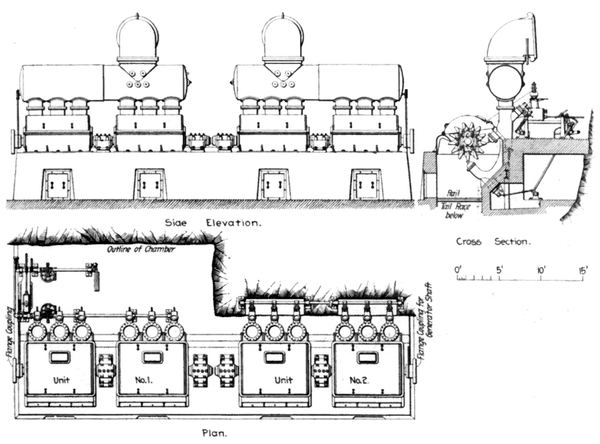 |
| Fig. 7.Elevation and Section of Water Motors. |
To handle the volume of water necessary to develop the power in each unit requires 12 jets, 3 ins. in diameter, discharging against six wheels. For convenience of bearing and shaft design these wheels are divided into two groups of three wheels each, each group being in a separate housing with a bearing between. This arrangement makes two groups of three vertical nozzle pipes each. Each pipe has flanged wings cast on each side, the flanges being bolted together. and the wings forming the back of the housing in which the wheels revolve.
| |||
| Fig. 8.Nozzle and Water Wheel for Exciter. |
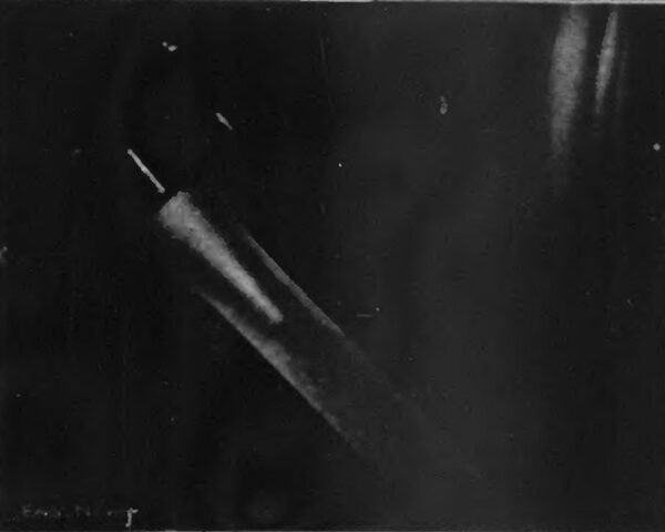
One of the special features of this plant is the regulating tips used on the nozzles. They not only throw a perfect and unbroken stream, but give absolute control over the quantity of water ap-piled to the wheels, and therefore over the power output of the unit. As these tips are controlled by the governor, the arrangement give an excellent degree of speed regulation with variable load at high efficiency. The tip has set within it a "needle" of bulb form with parabolic curves running to a point, and this needle is mowed in or out to give a greater or less width of the annular-opening between the tip and the wails of the nozzle. These tips are shown in Fig. 7. Fig. 8 shows this arrangement applied to the exciter unit, in which, however, the regulation is effected by a hand-wheel. Fig. 9 is from a flash-light photograph taken from the jet of the exciter. The full size of the jet is 3 ins., but when photographed it had been reduced to 2-1/4 ins. It clearly shows the solid, smooth stream, delivered with a head 253 ft., entirely free from swirling or other disturbance. This form of nozzle maintains this same condition from full jet size to 1-10 of the jet area. The regulating nozzles are operated from two long rocker-shafts, one controlling the upper, and the other controlling the lower nozzle tips. Both rocker-shafts are operated by a Lombard governor which is connected to the rocker-shaft by cranks and connections. The connections to each rocker shaft are so arranged with clutches that either or both rocker-shafts can be disconnected from the governor and operated or regulated by the hand-wheel on the pedestal stand. By this governor arrangement, with the regulating nozzle tips, the wheels use water in proportion to the power developed, so that the wheels are of a high efficiency at part load as well as at full load.
| |||
| Fig. 9.--View of Jet. |
| |||
| Fig. 10.Water Wheel of Main Unit. |
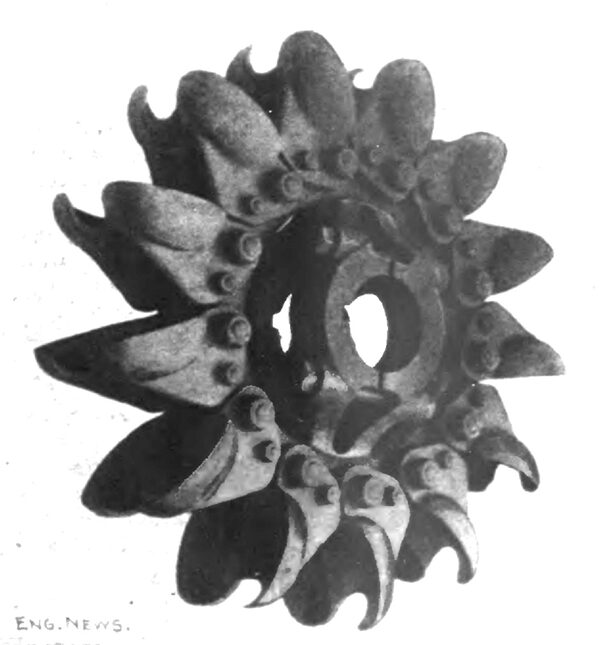
The wheels are of the type invented by Mr. W. A. Doble, of San Francisco. Cal., and were de-scribed by him in a paper on "The Tangential Water Wheel." read at the California meeting of the American Institute of Mining Engineers in September, 1S99. The particular feature is in the form of the bucket, which is termed the ellipsoidal bucket. This has a center rib to split the jet, and two hollow sides formed with correct curves to receive the water, reverse its direction and guide it to the edges of the bucket, where it is discharged. The lip of the bucket, however, is deeply notched in the center, so as to straddle the jet, which thus strikes the bucket with full force before it is broken by the lip passing through it. This secure an exceptionally high efficiency from the impinging jet, and the greatest value from the reaction of the water upon the bucket, while the wear on the bucket is reduced to a minimum, with a corresponding reduction the cost of maintenance. Should the erosion due to silt or gravel in the water reduce the efficiency by wear, the tips and buckets can readily be renewed at little cost. The wheels for the main power units are 45 ins. diameter, with split hubs and solid rims, and are pressed upon the 9-in. shaft, to which they are secured by a steel key. The split hub is drawn tight by four 1-3/4-in. steel bolts. Each wheel has 13 buckets attached to the rim by turned bolts. Fig. 10 is a view of one of these 45-in. wheels, showing the form of the buckets and the arrangement of the hub bolts. The six wheels are keyed on the shaft in two groups of three wheels each. The shaft is of forged steel, 9 ins. diameter and 24 ft. 5 ins. long. On one end of the shaft is a heavy flange coupling which is bolted solidly to the coupling on the generator shaft with turned bolts. The shaft is supported in two bearings of the ring-oiling, removable shell type. One bearing is at the extreme end of the shaft, and the second in the middle of the shaft length and between the two wheel housings. The generator bearing carries the other end of the shaft through the shaft coupling The bearings are bolted to heavy sole plates embedded in the concrete foundation.
The wheels are incased in sheet steel housing with cast-iron fronts, three wheels in each, so that there are two housings to each unit. The housings are made with the upper half removable to provide access to the wheels when desired. The cast-iron front of each housing is made of such form as to provide a deflector guard, which takes care of the water thrown from the wheels by the centrifugal action, and directs this water into the tail race, and thus prevents its being driven around the housing by the air currents which are created by the rapidly revolving wheels. In the top housing is a guarded opening to permit the indraft of air to replace that driven out of the housing and down the tail race by the rush of the water and the action of the wheels as centrifugal blowers. To prevent water from splashing out where the shaft passes through the side of the housing, the opening is protected with patented centrifugal disks and guard frames. Al-though this arrangement prevents the outflow or water, it permits a large and free indraft of air at this point also to replace that driven out by the action of the wheels and the water. Before this device was installed, regular packing boxes and glands were used, which required to be accurately in line; the packing required renewing, and care; and the bearings required lubrication. Taken altogether, the packing boxes were a source of annoyance and expense, besides setting up some little friction, and it is said that no matter how well the boxes were packed they always dripped water, whereas the large free openings of the centrifugal disk and guard are dry and clean.
Each wheel unit weighs about 100,000 lbs., in addition to the weight of water in the distributing receiver, and the nozzles; and in view of the high speed of the parts and the power developed, careful design and construction were required for the foundations. These are of concrete, built solidly into the floor and one side wall of the chamber. The waste water drops from the wheels directly into the tail race. The lower part of the steel wheel housing is firmly built into the concrete walls. A tunnel is provided under the governor platform for the lower rocker-shaft and connections that operate the adjustable tips of the lower nozzles, and thus make this operating gear accessible. The foundation for each unit is divided Into two compartments corresponding to the two wheel housings. A doorway, 2 x 3 ft., is formed in the front wall of each compartment, and four steel rails are built into the concrete across the opening into the tail race to support a temporary floor when it is desirable to enter the foundation to inspect the wheels or the nozzle tips, without removing the top wheel housing. All the hydraulic plant was built and erected by the Abner Doble Co., of San Francisco, Cal.
AUXILIARY APPARATUS.
The exciters are of 75 K-W. capacity, and are directly-connected to Doble tangential ellipsoidal water wheels of 45 ins. diameter, one of these exciter units being shown in Fig. 8. The wheels are mounted in steel housings, and are supplied with water through a regulating nozzle of 3-in. jet diameter, branching from a vertical pipe 12 Ins. diameter.
To make the chamber readily accessible for the employees and for the handling of supplies, an elevator is provided. This is operated by a winding drum which is driven by another tangential water wheel of 7 ft. diameter. A regulating nozzle with 1-3/4-in. diameter of jet is used for this work, and gives perfect control over the elevator cage. To permit cleaning the armatures of the generators while working, compressed air is available, being furnished by a vertical air com-pressor with cylinder 8 x 10 ins. Traveling the full length of the chamber are two 10-ton electric traveling cranes. These were used in installing the machinery, and are available to handle the upper wheel housings when it is desirable to inspect the wheels and for other purposes. The air compressor and cranes were built by the Abner Doble CO.
ELECTRICAL MACHINERY.
The completed plant comprises four generators of 1,500 K-W. capacity, built by the Westing-house Electric & Manufacturing Co., of Pittsburg, Pa. These are now working under full load. Each one complete weighs about 100,000 lbs. and stands 14-1/2 ft. high. They are of the revolving armature type and deliver a three-phase current at 1,000 volts, 7,200 alternations. Normal full load current is 1,000 amperes per phase. The armature winding consists of 266 bars with one bar per slot, and is a closed circuit winding. The armatures are 96 ins. diameter and weigh approximately 24,000 lbs. each. The speed is 300 revolutions per minute and the peripheral velocity is accordingly nearly 1-1/2 miles per minute. Massive collector rings of the ventilated type deliver current to the external circuits. Three brushes bear on each ring, and to insure equal division of current between them in case of unequal contact resistance, separate cable leads of considerable length connect the brushes and the outside circuit in order that the fixed resistance with each brush may he large compared with the possible variable resistance. The field magnet frame is split vertically and rests on the bed plate which supports the armature bearings. The two halves may be moved apart laterally for inspection or repair of parts. The pole pieces are laminated and are cast in the field frame. The field winding is of one layer copper strip, bent cold on edge and afterwards insulated. At each end of a coil are brass brackets which rigidly hold it on the pole piece, exposing both inside and outside surfaces to air circulation to carry away heat. This form of construction produces a coil that is very easily insulated, furnishes a maximum surface for ventilation, and may be easily repaired in case of ac-cident. At no load these generators require a field current of 95 amperes at about 90 volts, and with full non-inductive load, 100 amperes to maintain the same electro-motive force.
Speed regulation in a water power plant depends greatly on the kinetic energy in the moving parts. In these armatures, about 4,500,000 ft.-lbs. of energy is stored at 300 revolutions per minute, and from the construction of the water motors, the moving water column also contributes to the stored energy, since it operates directly upon the revolving parts of the water motor. The water column in penstock and receiver weighs about 600 tons, and with one water motor running has only 67,000 ft.-lbs. of kinetic energy, or about 1-1/2% of that in a generator armature. When all the water motors are in operation the water contains much more kinetic energy, but it is still of tittle importance compared with that stored in the revolving armatures. The stored energy in a single revolving armature is equal to the electrical output of that armature at full load in four seconds.
Two separate 125-volt exciters of 75 K-W each are provided for supplying field current the generators. They are separately driven by two 100-HP. Doble wheels, as already described. No automatic speed regulators are used here, since the load is perfectly steady, but regulation is effected by hand.
The switchboard is constructed of white marble, with mountings of brass and bronze. It is 35 ft. 5 ins. long and 7 ft. 6 ins. high, and has 18 panels, 4 for the generators. 2 for the exciters and 12 for the feeders. Current is conducted by lead-covered cables laid in sewer pipe in the cement floor, from the generators to aluminum bus bars extending along the south wall to the switch-board. These bars are supported by brackets on glass insulators. They are of pure aluminum, 0.2 x 3 ins. in section and in 30-ft. lengths. Three bars carry 1,000 amperes with a very moderate rise of temperature. The joints are lapped and bolted, and connection to the switchboard is made by cables with brass terminals, which are bolted to the bars. The exciter panels carry ammeters, circuit breakers, ground detectors, voltmeter plugged and rheostats. Each generator panel has circuit breakers on two of the three phases, synchronizing pilot lamps, field ammeter, a main ammeter on each of the three circuits, indicating wattmeters of the Niagara type, a field rheostat, double-throw three-pole switches. anti voltmeter and ground detector plugs. The feeder panel have circuit breakers and ammeters. The switchboard also carries three alternating current voltmeters on swinging brackets, by means of which the voltage in any phase of any generator may be read, connection with the various panels being made through the voltmeters bus bars. The wattmeters are arranged by a simple combination of series and shunt transformers. so that their indication Is the same as if they were on a two-phase circuit. This is of considerable value, all the indications of the meters remain equal with a balanced load even if the power factor on the three-phase circuit is less than one.
Fig. 11 is an interior view of the power chamber reproduced from a perspective sketch. The entire station, with its 10,000-HP. output is regularly operated and cared for by only two men on each shift; one is an electrician at the switchboard and in charge of the station, standing a watch of eight hours; the other is an oiler serving a 12-hour watch, whose principal work is that of inspection and keeping the entire station in good order. To better appreciate the contrast one may consider the crew required in a steam-driven station of equal output, including engineer, oilers, water tenders, firemen and coal passers. The first water wheel and generator in actual operation delivered current into Seattle on July 31, 1899 and into Tacoma, Nov. 1, 1899.
THE ELECTRIC CIRCUITS.
The transformer house at the head of the shaft is a fireproof building of brick and iron, with a concrete floor; it is 40 x 60 ft., 30 ft. high, and stands just east of and contiguous to the intake in this building, the current is received at an initial voltage of 1,000 and it then passes into Westinghouse step-up transformers where the voltage is raised to 30,000, which is the nominal voltage of transmission. The 1,000-voit current passes from the switchboard to the transformer house by cables of twisted aluminum wires. The conductors run first to the step-up transformers and thence to a second switchboard controlling the transmission lines. An elaborate high-tension plug board has been constructed overhead in this transformer house, by the use of which any combination of transformers and circuits can be arranged. There are similar plug boards at Renton, Seattle and Tacoma, and it is possible by the use of these plugboards conjointly to at range a combination so that a circuit may be Ina le from the Falls to Seattle and back to the Fails, then to Ta coma and back to the Falls again, a distance of 153 miles.
A RECORD FEAT IN LONG DISTANCE TRANSMISSION.
On Nov. 13, 1900, the company performed the remarkable feat in electric power transmission of driving an electric motor 153 miles distant from the generator. For several hours during the day the various services of the company were cut on and all the transmission lines were connected up in one continuous circuit, commencing at Snoqualmie Falls, running to Seattle, back to the Falls, then to Tacoma and back again to the Falls. The regular transmission is 32 miles to Seattle and 44 miles to Tacoma. The tests were conducted for experimental purposes only, and to show that electrical transmission of power can be made commercially practical at much greater distances than has heretofore been contemplated.
The single continuous three-phase circuit, 153 miles long, was composed as follows:
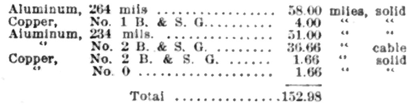 |
One of the Westinghouse 1,500 K-W. three phase generators furnished the current, and a similar machine was used as a synchronous motor at the end of the circuit. With the 153-mile circuit open at the incoming end, the tests were made for charging them at different voltages, the alternations (7,200) being kept constant. It was found that as the voltage increased, the charging current rapidly increased; at 22,500 line voltage it required 62 K-W. to charge the line, at 30,000 volts it required 112 K-W., and at 35,000 volts it required 180 K-W. With the lowering transformers at the Fails cut in and their secondaries open, it was found that the current required to charge the line increased; at 22,500 volts it required 76 K-W., and at 30,000 volts it required 123 K-W. The voltage at the incoming end of the circuit, with charging current only on the line, was greater than at the outgoing; 22,500 volts' out, gave 24,600 volts in, and 30,000 volts out, gave 32,100 in. Tests were also made to determine the different amount of charging current required at different frequencies, the voltage being kept constant at 30,000, and it was found that at 6,000 alternations, 100 K-W were required to charge the line; at 6,600 alternations, 105 K-W.; and at 7,800 alternations, 115 K-W.
The line was then tested for loss of power in transmitting a non-inductive load, consisting of the water rheostat at the Falls at the end of the 153-mile circuit. It was found that the line voltage out was 30,000, incoming 22,500, drop 25%. The amperes per phase at 1,000 volts out was 624; incoming, 354; loss, 11.2%. The total kilowatt outgoing was 1,100; incoming (that is delivered into the water rheostat tanks), 723; loss, 34.2%.
A test was also made for charging current with the sub-station transformers at Seattle and Tacoma, and the lowering transformers at the Falls in circuit, but with secondaries all open, and it was found that with the 30,000 volts out, there was 31,500 volts in, and that it required 193 K-W. t charge the line. A test was then made of operating a second generator as a synchronous motor at the end of the circuit and the machines were synchronized without any trouble whatever; but they soon began pumping, so that it was found advisable to separate the machines. During this test the outgoing line voltage had varied from 26,700 to 27,600 and the incoming from 24,000 to 26,700, giving approximately a drop of 6%. the amperes per phase at 1,000 volts out being approximately 900; incoming, approximately, 650; loss, approximately. 27.7%. Total kilowatts out. 432; incoming, 374; loss, approximately, 13-1/2%. The figures on this last test are approximate only, as all of the instrument needles oscillated very much, many of the ammeters fluctuating over the entire range of the scale. The foregoing losses would be greater or less according as the loads carried might he increased or diminished.
The experiment was then tried of operating the water rheostat and the synchronous motor in multiple at the end of the 153-mile circuit and the performance of the motor was very much improved. The water was then shut off from the water wheel and the driven motor immediately reverted to a generator driven by its own inertia; the current in the lines was reversed and the first generator became in turn a motor and ran at the other end of the 153-mile circuit until the inertia was expended.
THE TRANSFORMERS.
There are 13 transformers, each of 500 K-W. capacity, in the transformer house, arranged in two rows longitudinally, with an aisle space on each side and a 1,000-volt wire space between. All circuits entering the building are supplied with lightning arresters for the protection of the works. although lightning in that district is said to occur only at intervals of three or four years. Raising transformers are in delta connection for both primary and secondary circuits. Separate primary feeder panels are provided for each transformer, by means of which any transformer may be controlled at the switchboard. Each transformer panel is provided with a circuit breaker, a double-pole, double-throw washer switch, and an ammeter. Voltmeters for the entire board are supported on a swinging arm at one end. Groups of three feeder circuits have each a polyphase integrating watt-meter of the Westinghouse type. Leading up the shaft to the transformer house, are 24 bare aluminum conductors, carried on ordinary glass cable insulators on the timber frame work built in the shaft. The raising transformer are of the standard Westinghouse self-cooling oil-insulated type, and have a capacity of 500 K-W. each at 90% power factor. Their cases are 55 x 72 ins. and 66 ins. high, and contain 500 gallons of oil. This oil is of a brand made specially for transformer use by the New York Lubricating Oil Co., and claimed to be entirely free from acid and other matters injurious to insulation. The primary winding is for 1,000 volts and the secondary winding is for either 15,000 or 30.000 volts. Each complete transformer weighs, approximately, 10,850 lbs., of which 3,600 lbs. are in iron and copper. These transformers have a very low self-induction. With one of the windings short circuited, less than 3% or the normal E. M. F. at 7,200 alternations per minute will send full load current through the other coil. This is due to subdividing and closely sandwiching the primary and secondary coils, which are thin and flat.
The high tension coils have many layers, and but few turns per layer, and each layer is wound in the same direction, so as to reduce the difference of potential between the successive layers. At the end of each layer, the wire is carried across the face of the coil to the starting side. The low-tension coils are of bars or straps wound on edge and afterwards insulated. The coils are spread at the ends outside of the iron core to facilitate oil circulation which carries away heat, and also to increase the distance between the coils where it is difficult to apply solid insulation. To protect attendants and apparatus in case of accidental contact between high tension and low-tension windings, spark gaps are connected between each low-tension winding and the earth. Each transformer is supplied with, two high-tension fuse circuit-breakers by which it may be disconnected either by hand or automatically in case of excessive current load. The fuse circuit-breaker consists of two hinged wooden rods by which the fuse terminals are widely separated, breaking the arc when the fuse is ruptured by the current. The electric arc at 30,000 volts is 6 ft. long. Each incoming line wire is protected by a Wurts lightning arrester, of improved construction. On the front of a vertical slab, 24 x 65 ins., are mounted the spark-gap cylinders (in units of seven) in separate porcelain cases, while on the back of the same panel are six choke-coils mounted on three marble wings which support the coils and insulate them while they are brought in close inductive action with each other.
For the outlets, an insulated wall bushing is provided for each high-tension wire, consisting of a marble slab 24 ins. square set into the wall through the center of which passes a thick glass tube 24 ins. long and 2 ins. outside diameter which surrounds the wire. This is protected on the outside by a hood. The wires are led out from a cupola on the roof, occupying about a third of the length of the building.
The company has erected a brick building near the transformer house for use as a repair shop. with separate rooms for the machine shop, carpenter shop and blacksmith shop. The machine shop contains a 12-ft., 20-in. Lodge & Shipley lathe, a 28-in. Aurora drill press and a 24-in. Gould & Eberhardt shaper. This building also contains the company's headworks office and a storeroom.
TRANSMISSION SYSTEM.
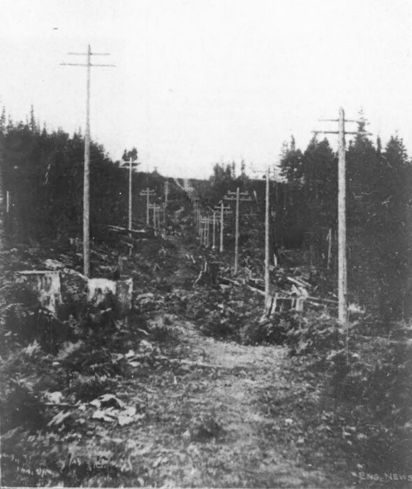
The country traversed by the transmission line, varies from mountainous to rolling and fiat. The right of way for the pole line is owned by the company with the exception of several stretches where the county roads are occupied under a franchise. The right of way is patrolled daily by men on horseback, each patrolman hiving a distance of ten miles, and reporting by telephone to Seattle and the Falls from the telephone booth located every three miles. This patrol service has been organized for the purpose of detecting any weakness that may appear in the line, and to protect it from any dangers that may threaten. The right of way is in general 50 ft. wide. In many places, however, the company has a timber right for a distance of 300 ft. on each side of the line, with the privilege of felling timber which might injure its operations. This right been exercised at considerable expense, and trees 8 or 10 ft. in diameter, 300 ft. high, and 300 ft from the line have been cut, assuming that if they fell they might reach the line and damage it. No falling tree can now reach the pole line. Fig. 12 is a view on the transmission line. The circuits are of stranded aluminum cables, and were the first instance of the use of this metal in long-distance transmission. The conductivity is about 60% of that of copper, so that the wire order to have a capacity equal to copper must have a cross-section about 66% greater, but with this increased size the weight is slightly less than 50% that of copper, Longer spans are, therefore possible, thus making a saving in poles and insulators. Aluminum is non-corrosive to a high degree, and has great tensile strength. From its larger area, as compared with copper, its radiating surface is larger and the wires keep cooler. Its cost is also less. The tie wires are of soft No. 8 B. & S. gage aluminum wire, and no electrolysis can occur with these ties, as would be the case with iron or copper wire. The aluminum transmission wires stop at the city limits of Seattle and Tacoma, and copper is used beyond these points for distances of 1-1/2 miles and 3/4-mile, respectively, The joints of the line conductors are spliced with the McIntyre sleeve, which consists of a flattened aluminum tube 9 ins. long and 1-16-in. thick, the diameter being sufficient to receive the two line wires. When the joint is made, it is given three to twists by special clamping tools. The aluminum wires were supplied by the Pittsburg Reduction Co., of Pittsburg, Pa.
| |||
| Fig. 12.View on Transmission Line. |
The poles are of cedar, 9 ins, diameter at the top stripped of the bark and either burned or tarred at the butt. The standard length is 36 ft., set 6 or 8 ft. in the ground, but the length ranges from 36 to 150 ft., according to the nature of the country. At the crossing of the channel in the harbor of Tacoma there are four poles about 154 ft. long, 47 ins. diameter at the butt and 23 ins. at the top, weighing 25,000 lbs. each. The poles were set in line with a transit and their lengths conform to grades established by the engineers.
The cities of Seattle and Tacoma are reached by separate pole lines. These are parallel and 40 ft. apart, as far as Renton, 19 miles, where they diverge to their respective terminals: Seattle, 31 miles and Tacoma 44 miles. The Seattle lines contain about 67,000 lbs. of wire, and the Tacoma lines 72,000 lbs. The charging current on one of the Tacoma lines on open circuit at 30,000 volts is 7.4 amperes, which is small, compared with the load current, so that no trouble is experienced from static capacity. The lines are of aluminum, approximately 0.26 ins. diameter for the Seattle circuits, and 0.23 ins. for the Tacoma cli cults. and are designed to deliver respectively 4,000 and 2,000 kilowatts at 25,000 volt pressure and 80% power factor. Measurements made on the Seattle line show a resistance of 84.5 to 88 ohms, depending on the temperature, and reactance at 7,200 alternations equivalent to 54 ohms, for a circuit composed of any two wires. The resistance of any two wires of the Tacoma circuit measures 152 ohms.
The lines are carried on triple-petticoat Imperial porcelain insulators of the Redlands type, 41/2 ins. high and 6-1/2 ins. diameter, weighing 4 lbs. each. The pins are of locust, boiled in paraffin oil, and carry the insulators 4 ins. clear above the cross-arms. Two circuits are run on each pole line, one on each side, with a triangular spacing of 30 ins. between wires. On the lower cross-arm are four wires, the inner ones 75 ins. from the center of the pole, and the others 25 ins. from them; on another cross-arm, 251/2 ins. above, are two wires, each 40 ins. from the center of the pole. The cross-arms are 4-1/2 x 6 ins., 8 and 10 ft. long. The whole line is substantially built, with poles braced whenever necessary, while double cross-arms are used on all curves and turns and crossings. The length of span on the Seattle line varies from 90 to 150 ft., but the average is 110 ft. On the Tacoma line, the average span is 150 ft. A sag of about 15 ins. is allowed, this being considerably greater than is common practice with copper wires. The lines are divided into six equal sections on either side of the Renton sub-station by means of transpositions. The spans in which these transpositions are made are between poles set 6 ft. apart, which effectually prevents accidental contact between wires. At each transposition the circuits are given one-third of a turn, always in the same direction.
A telephone line of No. 10 B. & S. gage aluminum wire is carried about 5 ft. below the power circuits on ordinary glass insulators on brackets. It is transposed at every fifth pole. The patrol men carry portable telephones, so that a call can be made by climbing any pole. Telephone booths, containing also line supplies and tools, are located at intervals of three miles. The telephone instruments are of the Stromberg-Carlson type.
SUB-STATIONS.
The first sub-station is at Issaquah, ten miles from the Falls. This is a coal mining settlement of about 1,200 people. Here a small brick station has been erected, from which to distribute current for lighting the town and furnishing power to the coal mines. The station serves also as a residence for the patrolman on this section. The next substation is at Renton, 19 miles, where a brick building, 40 x 40 ft., 22 ft. high, has been erected for the high-tension apparatus and power apparatus, and this also forms the home of the man who has charge of the station and patrols the adjacent section. The high-tension wires enter the building through marble and glass bushings, and there is a high-tension switchboard, similar to that at the generating station, which admits of making any combination of the incoming and outgoing circuits. Each wire has a high-tension fuse switch. The town has a population of 2,000, and is in a farming district. Extensive coal mines in the neighborhood are expected to be eventually operated by electricity furnished from this station.
The Tacoma circuits pass through Auburn and Kent, each having a population of about 1,000, and being in a farming and dairy district. A small sub-station has already been established at Auburn, 31 miles from the Falls, and another is to be established at Kent, 25 miles. The former place is on the Northern Pacific Ry., where its lines from Seattle and Tacoma meet the main overland line. The terminal sub-station at Seattle is a substantial stone building, two stories high. The machinery occupies the basement, while the company's offices and rented offices occupy the first and upper floors. The terminal sub-station at Tacoma is a red brick structure, occupied jointly with the Tacoma Railway & Power Co. Here a high-tension switchboard has been installed, the current being used for lighting and power purposes.
The Seattle sub-station is in the business district, and the high-tension wires are carried to it on 70-ft. poles, painted blue and black in order to make them distinctive. The wires enter a tower on the third floor, about 40 ft. above the ground, and are led through a terra cotta shaft to the lightning arresters on the second floor. These are six in number and similar to those at the station at the Falls. On the ground floor are high-tension fuse-switches by which the incoming current may be controlled. All of the load may be placed on either transmission circuit, or it may be divided so that the steady load is on one circuit and the fluctuating load on the other, or both circuits may be connected in multiple. The switching apparatus is of extreme flexibility. There are also high-tension fuse switches for the lowering transformers in the basement.
There are at present three step-down static transformers with primaries and secondaries in delta connection, for supplying 350-volt current to the 500-volt rotary transformers. The primary coils may be connected either for 12,500 volts or 25,000 volts. The secondary coils have intermediate terminals by which the E. M. F. supplied to the rotaries may be adjusted when necessary. Otherwise the transformers are similar in construction and capacity to those of the generating station. There are also four pairs of two-phase to three-phase lowering transformers of 300 K-W. capacity each, and two pairs of 500 K-W. each, with 2,000-volt secondaries for general lighting and power distribution, which makes the total station transformer capacity 3,700 K-W. Fig. 13 is a view of the interior of the Seattle sub-station.
White marble switchboards are furnished for controlling the three rotary transformers. Each of the alternating current panels contains a three-pole single-throw washer switch, three ammeters. synchronizing lamps, field rheostat and a switch for the starting motor on the rotary. On each direct-current panel are a circuit breaker, ammeter, volt-meter, plug receptacles, and two single pole washer switches. The feeder panels have circuit breakers, single-pole washer switches and Thomson recording watt-meters. Volt-meters are mounted at the end of the board on a swinging arm.
There are two rotary transformers of 500 K-W. capacity delivering current at 550 volts, which are operated in multiple on both alternating and direct current sides. A third has been ordered. These transformers have 18 poles, and the speed is 400 revolutions per minute. Collector rings and brushes are like those on the generators but of smaller capacity. To bring the rotaries in synchronism without excessive starting current, a small induction motor is mounted on the armature shaft. As this has 16 poles, it is enabled to bring the rotary armature slightly above synchronism, but the final speed adjustment is made by varying the field current which imposes more or less load from iron loss in the rotary armature. Several cross connections in the armature windings insure superior mechanical and electrical performance. For alternating current lighting and power motor work a panel is provided for each set of three-phase, two-phase transformers, containing two 2,000-volt automatic circuit breakers, two ammeters, two Niagara indicating wattmeters, two double pole throw switches and pilot lamps. The feeder panels are the same, except that polyphase integrating watt-meters of the Westinghouse type are used instead of the indicating watt-meters. In making changes on these boards the circuits are first opened by the circuit breakers, as the switches are not designed to break current.
The Tacoma station is equipped with three 500 K-W. transformers and two 200 K-W. transformers, similar in type and style to those at Seattle, making 2,100 K-W. total capacity at Tacoma.
UTILIZATION OF THE POWER.
The Snoqualmie Falls Power Co. furnishes power for both lighting, railway and general power purposes, and it Is expected that many of the manufacturing plants of Seattle and Tacoma will soon be operated by the power from Snoqualmie Falls. The power in Issaquah, Renton and Auburn is used for lighting purposes only, for both incandescent and arc lights. In Seattle, all the stationary motors are being operated, and the entire municipal street lighting system; also the Centennial flour mill, 2,000 barrels daily capacity, the Capital flour mill, 300 barrels daily capacity, and about half the street railways. All the street railways will soon be operated from this service. In Tacoma, the municipality owns the lighting system and power Is purchased for the purpose of running it. The Snoqualmie power is furnishing nearly all the lighting circuits in Tacoma at present, and the others are to be added as soon as the transformers have been changed to adapt their distribution to the frequency of this plant. The cable railway in Tacoma is also operated by an induction motor applied to the cable driving machinery. All the electric roads are under contract and will take the current as soon as the induction motors which are to drive a line shaft have been installed. An induction motor is also employed at Tacoma in an elevator for loading ships. The manufacturing plants in Seattle and Tacoma include three flour mills, a smelter, car-shops, several Iron works, elevators, machine shops, etc. The operation of the municipal waterworks pumping station for Tacoma Is also contemplated. Negotiations are also in progress for the establishment of electrolytic and chemical works. Almost the entire output of power was contracted for before the Snoqualmie Fails power plant was in operation. The first customer was the Centennial Flour Mill Co., of Seattle, which contracted for power nearly a year before the completion of the plant. All the machinery for operating the mill, including that for grinding, cleaning, ventilating, receiving and delivering the grain and flour by elevators, etc., is operated by two Westinghouse motors of 200 HP each, which have entirely supplanted the steam power equipment. A third 200-HP motor has been ordered, so that the capacity of the mill may be increased.
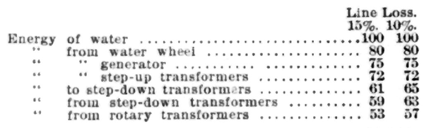
The plant now installed develops a total of 10,000 HP., of which 66% is for use at Seattle. Taking the energy of the water at the Falls as 100, the percentage available at the time of full load at different points in the system is given in the following table. The first column of this table is computed for a line loss of 15%, but it is intended to increase the amount of wire on the line, so as to reduce the loss to 10%:
 |
The city of Seattle has a population of 80,600; Tacoma, 38,500, and Everett, 10,000. These three cities, and the neighboring towns are rapidly growing and increasing in industrial importance, and many small industries and factories, large in aggregate, are being established. The Snoqualmie Falls Power Co. does not engage in the distribution of power to small customers, but sells power in large blocks for this purpose to the Seattle Cataract Co., and the Seattle Electric Co., in Seattle, and the Tacoma Cataract Co. and the Tacoma Railway & Power Co., in Tacoma. It reserves for itself the duty of supplying large plants of every description which can be reached by any of its lines or extensions. A transmission line to Everett is proposed, 35 miles from the Falls, where a paper mill, smelter and other industries in operation would take current amounting to 2,000 HP. The company's policy is to build up a business of large volume at moderate prices, rather than small volume at high prices. The natural conditions are said to make this power one of the cheapest of development in the United States, and therefore the company is able to offer specially low rates.
It has already been noted that the shaft will accommodate another penstock of the same capacity as the one now installed. The intake and tail race have also been built for a plant of double the present capacity. The poles will accommodate twice as many wires; the right-of-way has been bought and improved sufficient for any expansion, and the sub-stations will accommodate machinery for several times the initial power. Another chamber and additional machinery and wires are the only extensions necessary to double the capacity of the plant.
