[Trade Journal]
Publication: American Institute Of Electrical Engineers
New York, NY, United States
p. 597-618
CONTINUITY OF SERVICE IN TRANSMISSION SYSTEMS.
BY MAGNUS T. CRAWFORD
INTRODUCTORY STATEMENT
The object of this paper is to give the results of a number of years of operation of the Snoqualmie Falls Transmission system of the Seattle-Tacoma Power Company and to deduce therefrom practical conclusions as to the effectiveness of the method of operation used. The discussion will be confined entirely to the transmission system, and the possibilities of insuring continuous service by means of auxiliary steam plants will not be considered. Each high-tension system is a problem in itself and must be worked out with respect to its individual features and conditions, such as generating capacity in kilowatts, length of lines, size of wires, ratio of resistance and reactance, line voltage and climatic conditions. It is believed however, that a log of the operating results of a particular system is worthy of record, if the conditions of operation are correctly described.
DESCRIPTIVE DATA
The general features of the system are shown in the accompanying diagram and illustrations.
A good description of the original installation as completed in 1900 may be found in Engineering News, December 13, 1900, and the evolution of the transmission line was described in a paper read before the Seattle Section of the A.I.E.E., December 19, 1908, published in the PROCEEDINGS, and in the Journal of Electricity, April 24, 1909. This paper covers only the four years 1907, 1908, 1909 and 1910.
1907
Generator capacity 12000 kw., step-up transformers 15,000 kw. Transmission 30,000 volts three-phase, neutral ungrounded.
Poles. Cedar, average height 40 to 50 ft. (12.19 to 15.24 m.).
Spans. 135 to 160 ft. (41.14 to 48.76 m.) average length; up to 1000 ft. (304.8 m.) at river crossings.
| |||
| Diagram of 60,000-Volt Transmission System |
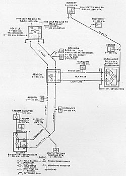
Lines. Falls to Renton 20 miles (32.18 km.) two pole lines. Renton to Seattle 13 miles (20.92 km.), two pole lines. Renton to Tacoma 26 miles (41.84 km.) by one pole line and 34 miles (54.71 km.) by the other. Falls to Everett 40 miles (64.37 kin.) one pole line. Tacoma to Smelter at Point Defiance, 6 miles (9.65 km.) one pole line. Total 172 miles (276.8 km.)
Wires. Falls to Renton No. 4/0 seven-strand aluminum. Renton to Seattle and Tacoma, No. 2/0 seven-strand aluminum. Falls to Everett, No. 4 solid copper. Tacoma to Smelter, No. 4 solid copper.
Spacing. 7 by 9 ft. (2.13 by 2.74 m.) and 7 ft. (2.13 m.) equilateral triangles.
Insulators. One piece, triple petticoat porcelain, 6 in. (15.24 cm.) diameter, Redlands pattern. White imperial porcelain on main lines. Brown porcelain on Everett line, not tested before installation.
Pins. Locust wood, impregnated with paraffine.
Cross Arms. Four by 5 1/2 in. (10.1 by 11.13 cm.) to 5 by 6 in. (12.7 by 15.24 cm.) select Washington fir.
Switches. At Falls, non-automatic remote control, vertical break oil switches in brick compartments. At Renton, Seattle and Tacoma, nonautomatic lever control, rotating horizontal break oil switches in iron tanks. At small stations and for throwing lines in multiple, fused air break " jack " switches or fused horn switches.
Protective Apparatus. Multigap lightning arresters with series resistances.
1908
Wood pins changed to malleable iron on corners and important points.
1909
Transmission voltage raised to 60,000 volts on December 6, 1909, using same, wires, poles and cross arms.
Insulators. Four-piece brown porcelain of standard design, each tested to 120,000 volts, and made with threaded (38.1 mm.) pin hole.
Pins. Malleable cast iron with threaded head.
Switches. At Falls and Renton, non-automatic remote control, vertical-break oil switches in steel tanks. At Seattle, Tacoma and Everett, non-automatic lever control rotating horizontal-break oil switches in iron tanks. At small substations, series trip coil actuated automatic overload release, rotating horizontal break oil circuit-breakers in iron tanks.
Disconnecting Switches. Out-door pole top type, three-pole double break, consisting of contact jaws mounted on line insulators with connecting blades rotating in a horizontal plane.
Protective Apparatus. Aluminum cell electrolytic lightning arresters installed at each end of each line.
1910
Additional 8750 kw. generator put in service in November, with 7500 kw. additional step-up transformer capacity.
OUTLINE OF SYSTEM OF OPERATION
In the operation of high-voltage lines on the Snoqualmie system the high-voltage line switches are non-automatic electrically-operated by remote control except those used in throwing the lines in multiple at substations, which are instantaneous overload release switches. The Falls operator has on his switch?board an indicating ammeter and the control handle for an electrically-operated remote-control oil switch for each outgoing high-voltage line.
The generator oil switches arc kept blocked in solid on the bus bars except when synchronizing a new machine. If the Snoqualmie system is running in parallel with the Electron system or with other generating systems as is frequently the case, the connection is made with instantaneous overload-release circuit-breakers, and a similar connection is made with the steam plant at Seattle.
When a short circuit comes on the system all automatic circuit breakers connecting other systems and all switches for multiple connections drop out at once, leaving each line separate clear to the Falls. The Falls operator first lowers the voltage and gets the speed of the machinery under control. It is then usually apparent on the line ammeters which line is short circuited, and if it does not burn clear in a few seconds it is opened with the remote-control oil switch. The voltage is then slowly brought back to normal and only a part of the load is lost. The substation operators then open their end of their line at the pole switch, and linemen are sent out to the defective section of the line. This is located by opening all pole switches in the line and then testing out one section at a time, starting at the Falls, until a section is found which shows trouble.
If it is not apparent to the Falls operator which line is in trouble, the short circuit is fed thirty seconds, and one of the lines opened, and if it still does not clear it is fed thirty seconds longer on the other line, and the station is never shut down as long as it can be kept running. Two large water rheostats of iron wire immersed in the tailrace and provided with oil switches are thrown on the generator bus whenever a heavy load is to be dropped, as in opening a short circuited line, and serve to aid the control of speed and voltage. In extreme cases where trouble holds and all lines are opened, the station is run on the water rheostats and each line thrown in again at intervals until one is found that is clear.
Substation operators open all high-tension switches when power goes off the line and immediately make connections with another generating system or steam plant, and pick up the local load until power comes on the lines again.
The details of the system of upkeep employed in connection with the transmission system have been carefully worked out, as a great many of the interruptions in service may be avoided by proper maintenance of the lines. Eight patrolmen are employed and each held responsible for the condition of a part of the line. They are stationed at a transforming station as near as possible to the middle of their patrol, and furnished with a residence and a telephone from the private line. Patrolmen are furnished with a saddle horse and saddle bag containing telephone test set, sundry tools and material, and once each week they carefully inspect their section of the line. All badly broken insulators are replaced and any other necessary repairs made. Every two miles along the line a small booth is fastened to a pole, and a stock of insulators, pins, cross arms, line wire, etc., are kept locked up therein, so that in case of trouble, material for repairs will always be within one mile.
Each patrolman also has charge of the pole switches in his territory and once a month he makes a complete and thorough examination of each switch, keeping the parts well oiled and in perfect alignment. Each week he makes a written report on a printed form of the results of his line patrol and switch examination.
When any repair work is to be done on a high-tension line, it is killed and opened by an air-break switch at each end, and the lineman working on the line makes a solid short circuit and ground at the point where he is working, with a flexible cable provided for the purpose. All lines are in charge of the station operator, and linemen notify the operator by telephone when a line is desired, waiting until he is told the line is dead before doing any work thereon. All communications between employees in connection with high voltage are repeated back to the speaker, and are written down in the station log book. These precautions are necessary to reduce mistakes to a minimum.
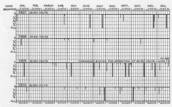
EXPLANATION OF TABLES
The following tables and curves show a log of the operation of the transmission system for the last four years. All cases of trouble on the high-tension lines or in transformers that caused an appreciable disturbance of the line voltage are recorded, but short circuits on low-tension distribution systems and other troubles not chargeable to the transmission system are excluded. The times given as " shut down " are cases where power was off the high tension lines of the Snoqualmie system long enough to switch out the defective line. The actual service interruptions were of very short duration, as power was usually obtained immediately from another system or steam plant at Seattle, Tacoma and Everett.
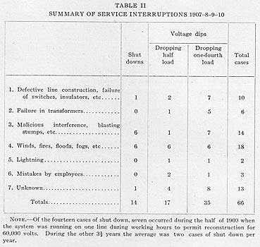
The conditions of transmission are somewhat severe, as the lines pass through rough country and along country roads. The land is being cleared for agricultural purposes and for new railroads, so that a great deal of blasting and grading is being carried on, causing much trouble. The pole line has been built ten years, and has not the mechanical factor of safety of a new line. The tables show how the troubles resulting from these adverse conditions were handled with a minimum disturbance to service, as out of the total of 66 cases of trouble given in the table, 52, or about 80 per cent, were handled without an interruption of service.
| |||
| Service Interruptions on the Snoqualmie Transmission System |
During the latter part of 1907 considerable trouble was caused by burned wooden pins. These pins had been in service nearly seven years, and the threaded tops were softened to pulp, apparently by the action of nitric acid formed from the air and moisture by the leakage currents.
The line was gone over by patrolmen and on all turns and important places the wood pins were replaced by malleable iron pins, and no more trouble resulted from this cause. With the weak points thus fixed the system gave practically continuous service during the year 1908. During 1909 the work of recon?
(missing pages 603-610, too technical)
·
·
[Missing text]
·
·
|
DISCUSSION OF RESULTS
Before discussing the above results, a definition of continuous service is necessary. In cases where only a voltage dip is shown, the bus voltage of 115 volts dipped down to some value between 40 and 90 volts for a few seconds and then returned to normal. To the lighting consumer this is not objectionable if it does not occur too frequently. To the small power consumer, such as shops and industries using motors in small units, generally speaking it is not a serious inconvenience, as the motors will often come back up to speed and will at most only require restarting. In the case of very large power units, they will usually stay in on the line unless they are heavily loaded or the dip is too prolonged.
The 500-kw. synchronous converters on the system almost always stay in and are not cut off until the current goes clear off the line. On the other hand if the voltage dip is very sudden in its return to normal voltage, large synchronous machines are much more apt to be thrown out. In the above table there are 52 cases where the voltage dipped but the system was not shut down, and in only 17 of these cases was the dip sufficiently prolonged to lose any considerable amount of load. In the other cases practically all the large motors stayed on the line. It seems reasonable then to conclude that moderate voltage dips of short duration do not constitute an interruption worth considering.
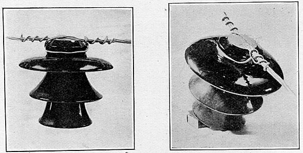
| |||
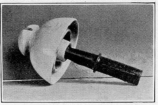
| Porcelain Insulator and Iron Pin Used on 30,000-Volt Line |
In cases where the voltage gets to a very low value and does not return to normal for ten seconds or more, the most of the power load will be dropped, but the lighting load will be returned. The power consumer is then put to the inconvenience of stopping work long enough to start up his motors again. The railway station operator must synchronize his converting units again, but if the drip is not over thirty seconds they should still have considerable speed and this should only be a few minutes work, which is not a hardship to railway service. Some power installations will suffer great inconvenience, such as for instance an ammonia compressing outfit, and also some electrolytic processes, where even a momentary shut down will cause heavy loss. However, such consumers will only form a small percentage of the average power company's business, and any expensive equipment to insure them absolutely continuous service should be a part of their own installation.
In cases where power goes completely off, all load is dropped and all consumers suffer maximum of inconvenience until service is resumed. The gross income of the power company practically ceases and the operating expenses continue, besides the loss in good will which can not be measured. If service is resumed within five minutes, the average consumer will hot suffer serious loss, but where the shut down extends over thirty minutes or an hour the financial loss and inconvenience is very considerable to all parties concerned. We may then conclude that prolonged voltage dips are an inconvenience but if of infrequent occurrence are not serious menaces to satisfactory service, whereas complete shut-downs cause heavy loss. Speaking from the average consumers viewpoint, commercially continuous service may include infrequent voltage dips and very rare shutdowns of periods never exceeding five minutes.
| |||
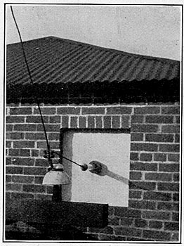
| 30,000-Volt Entrance Construction |
Causes of Troubles. The first two causes in Table II are defective construction and apparatus, and burn-outs of machinery. By testing all line insulators for a voltage a little over twice normal and carefully testing all machinery winding before installation the entire system may be made to withstand double normal voltage for several minutes without failure of insulation. This means that transient voltages considerably in excess of double normal voltage can be withstood, as brought out by Steinmetz and Hayden in a paper before the A.I.E.E. in June, 1910. By installing protective apparatus such as air relief gaps which are set to break down at double voltage and which have a time lag much lower than that of the insulation of the system, practically all destructive surges can be taken off the system. This may be done by installing electrolytic lightning arresters at the entrance to all important stations. If lightning becomes so troublesome as to shatter insulators on the line where it strikes at some distance from an arrester, relief gaps may be installed at each insulator if necessary, by means of arcing rings as described by Nicholson in a paper before the A.I.E.E., March 30, 1910. In this plant, however, lightning strokes on the line are very rare, and by using wood poles and cross arms, an entire pole may be burned down without interrupting service if the wires are not broken. The first two causes of trouble and also the sixth can thus be reduced to a minimum by properly testing the insulation of apparatus and the installation of protective apparatus.
| |||
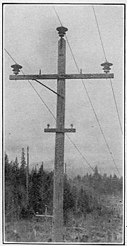
| Pole-Top Construction at Square Turns. (60,000 Volts) |
| |||
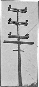
| Pole-Top Construction Where Two Lines Are on the Same Pole, Showing Guard Wires Over Railroad. (60,000 Volts) |
Blasting stumps is a source of much annoyance in this section of the country, and can best be handled by a campaign of publicity. The patrolman on each section of the line should make it his business to become personally acquainted with all the ranchers enroute and keep his eye open for all -evidences of preparation for clearing land, and when he sees blasting is to be done call attention to the notices of warning kept on each pole, and show every desire to cooperate with the parties concerned and have the line killed before blasting is done. Deliberate interference should be prosecuted vigorously by arrest and fine where possible.
| |||
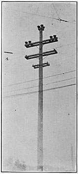
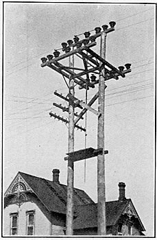
| Pole-Top Construction on Main Lines. (60,000 Volts) |
| |||
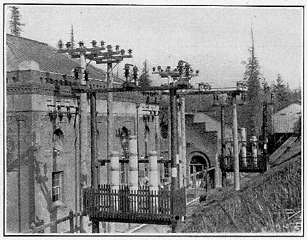
| Entrance Tubes at Substations. (60,000 Volts) |
Troubles from winds, fires, floods, etc., can be mitigated by using a very large factor of safety in the mechanical construction of the line, and by putting the high tension wires at a good height above all telephone and other wires easily broken. Structures in soft soil should be set solidly in rock boxes and well braced, lines taken via separate routes whenever possible, and always on separate pole lines. All large trees that can blow into the line should be bought and cut down, and the brush kept closely cut on the right of way.
| |||
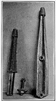
| Malleable Cast Iron Pins. Cross-Arm Pin Fits 1 ½-In. Hole in Old Crossarms. T-Headed Bolt Slips Into A Seat on A Shoulder Cast on Inside of Shank at Bottom, and is Tightened Up Under Cross-Arm. Weighs 3 ¾ and 7 Lb. Ultimate Strength 1800 Lb. at Line Wire. (60,000 Volts) |
| |||
| Standard Pole Switch. (60,000 Volts) |
Mistakes of employees can be reduced by providing them with definite written instructions on their duties and course of action under various conditions and by providing them with the best working equipment. Station operators in a plant employing non-automatic operation are very important units in the system; a little welfare work and good pay to good men, and in fact anything that will make them take interest in their work and pride in good results will prove an excellent investment.
| |||
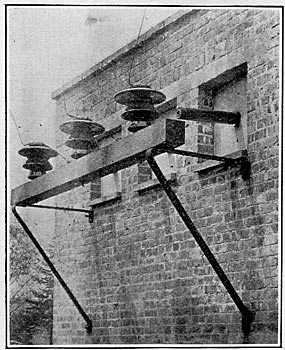
| Switching and Lightning Arresters at Snoqualmie Falls |
Results of Method of Operation. The standard practice in the operation of duplicate transmission lines is to install automatic overload relays and circuit breakers on each line at the generating station, and reverse current relays with automatic circuit breakers at the substation. Even with complicated systems this idea may be carried out so that theoretically a short circuit anywhere on the system will automatically be cleared and the defective line cut out. The experience of this company has been that practically better results can be obtained by placing the control of the high-tension lines in the hands of a carefully trained operator. From the operation of this system it is believed that the non-automatic method of operation is less apt to produce destructive oscillations when a short circuit is being cleared from the system. Taking for instance a case where a piece of iron wire is thrown across the line. There being no automatic regulation except slowly acting water wheel governors, the speed and voltage of the generating units dip severely. The operator encourages this and blocks the action of the governors, feeding the short circuit at the reduced voltage. The low-frequency high-power surge first set up by the short circuit may thus be reduced in intensity, being also dissipated by the resistance and cushioned by the reactance of the line, and the station is then simply running on a severe overload for a few seconds. If it is apparent which line is short circuited, it may then be opened with safety. If on the other hand the voltage and speed are automatically held up as far as possible by Tirrill regulators and governors, and the surge is ruptured at a point other than zero in the wave, a destructive potential will result which may cause damage.
In the case of an arcing ground a more severe condition exists than in a short circuit, as in cases where one line wire is whipping around on the ground, making and breaking contact. In this system where the neutral is ungrounded severely unbalanced strains may be produced in this way, as is shown by the puncturing of generator and transformer windings in such cases. An arcing ground was not always visible on the line ammeter, and an electrostatic ground detector was installed on the generating bus. This indicates promptly all high-tension grounds, and the telephone circuit along the same poles is an instantaneous indicator showing which line is grounded. Grounded lines are cut out without attempting to burn clear, and the installation of electrolytic arresters on the lines, transformers with reinforced insulation on the end coils and static relief gaps on the generating bus bars has given entire freedom from trouble from arcing grounds, as shown by the absence of failures of insulation since the installation of the new equipment in 1909.
| |||
| Showing Type of Tie Used and 60,000-Volt Insulator. 4/0 Seven-Strand Aluminum Cable With No. 2 Tie Wire. |
Since the change to 60,000 volts it has been the practice to open the defective line if it does not burn clear in about five to eight seconds instead of holding for thirty seconds. By the installation of a Tirrill regulator with a special relay for lowering the voltage during a short circuit the operator does not have to look after the voltage, and with accurately reading deadbeat line ammeters he is able to see the situation inside of five seconds. This equipment has been recently installed. The switches for multiple connections now installed on the low-tension side at substations work instantly instead of in the slow uncertain manner of the old 30,000-volt fuses used for this purpose, so that much better performance can be expected in handling short circuits in the future.
