[Trade Journal]
Publication: World's Fair Electrical Engineering
Chicago, IL, United States
vol. 1, no. 5, p. 287-291, col. 1
THE ELECTRIC POWER CIRCUITS AT THE WORLD'S FAIR.
BY L. S. BOGGS, ENGINEER IN CHARGE OF ELECTRIC POWER.
In addition to the numerous circuits transmitting current for arc and incandescent lighting, so fully described in the earlier numbers of WORLD'S FAIR ELECTRICAL ENGINEERING, there is also an independent set of eight circuits designed for electric power service only. These circuits extend either directly or by means of tap-wires into all the principal buildings and have a total length of 95,000 feet, insulated with 1/8-inch wall of rubber, over-braided.
 |
| Fig. 1. |
These circuits are numbered respectively from i to 8, and are distributed about the grounds in the following order, it being understood that the cables pass down into the subway from the respective blocks containing the generators, as fully described and illustrated in the January, February and April numbers of this magazine. Circuits Nos. i to 7 will convey current of 500 volts potential; circuit No. 8, current of 220 volts potential.
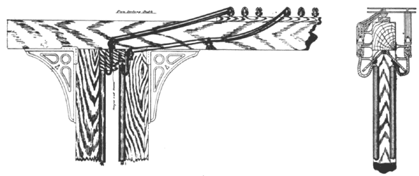
Circuit No. 1 supplies the necessary current for operating the motors in the Transportation building and the annex thereto, and consists of ten 0000 cables that pass down from the C. & C. generators into the subway, and from the northwest corner of the annex to Machinery hall are carried onto the elevated structure (see Fig. No. 1) to the west center of the Transportation building, where a distribution of current, aggregating 200 horse-power for the Transportation building and an equal amount for the annex, is arranged for, making a total of 400 horse-power. Current may also be taken from these circuits not only for motor service, but also for so-called "incandescent arc lamps," operated in series of ten on these 500-volt circuits, to illuminate the interior of the annex to Transportation building.
 |
| Figs. 2 and 3. |
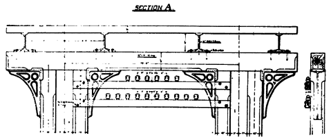
Circuit No. 2, consisting of four 0000 cables, passes through the subway to the center of the Government building, where two of the cables are carried into the building to operate motors, 50 horse-power capacity of which are already placed, and the remaining two cables extended to the Fisheries building, to supply the current required by two C. & C. motors that operate the circulating pumps connected to the tanks. Here the circuit is reduced to two 0 wires and carried up through tubing and attached to insulators supported on a series of special cross-arms fastened beneath the roadbed of the elevated railway structure, as shown in the accompanying illustrations (Figs. Nos. 2 and 3), and thereon passes around the north end of the park and as far south as the west center of the Woman's building. From the Woman's building a circuit of two 0000 wires extends south and east to the power plant, the two o wires being the connecting loop for the two arms of this circuit that has a total length of 28,930 feet. At the station of the Weather Bureau this circuit is tapped for current to operate a 5 horse-power motor; at the New York State building for a 25 horse-power C. & C. motor; at the Woman's building for two 20 horse-power motors for elevator service; at the northwest corner of the Horticultural building for a present aggregate capacity of 50 horse-power; and at the Service building for current to operate ventilating fan-motors of 3 horse-power and 5 horse-power capacity.
From the northwest corner of Machinery hall, power circuit No. 3, consisting of four 0000 wires, passes onto the elevated structure and is carried around to the east center of Midway Plaisance. Here it is divided into two circuits each of two 0000 wires and carried in the Plaisance on handsome octagonal poles that are placed on each side of the Midway close to the fence. This circuit extends through the Plaisance and is tapped at frequent intervals to supply current to operate motors in this great foreign mart. The capacity of this circuit exceeds 200 horse-power.
Circuit No. 4, consisting of six 0000 cables, leaves Machinery hall at the southeast corner, and through ducts extends to and along the elevated structure to the east center of the Dairy building, where a 17-1/2 horse-power motor is utilized in driving a refrigerating machine and a 30 horse-power motor belted to line-shafting. At the southwest corner of Agricultural annex a tap-line conveys current to six motors, one of 70, two of 60, and three of 30 horse-power each, that are driving line-shafting.
Circuit No. 5, consisting of six 0000 cables, leaves Machinery hall at the southeast corner and is supported beneath the elevated structure to a point near the southwest corner of the Agricultural annex, then down through tubing and underneath the docking to the middle of the Casino pier, where it supplies the feeder-wires with 300 horse-power in current to the motors that operate the movable sidewalk described elsewhere in these pages. Circuit No. 6, four 000 wires, conveys current to the Manufactures building, where an aggregate capacity of 150 horse-power in motors will be in service.
Circuit No. 7 supplies 400 horse-power in current to the Mines and Mining building, with the aid of six 0000 cables, operating two 150 horse-power motors belted to line-shafting, and one 6 horse-power and one 17-1/2 horse-power motor connected to pumps, while additional motors are being attached.
Circuit No. 8 passes down from the C. & C. bus bars to the subway, and from thence in ducts to the southeast pavilion of the Administration building, and conveys 200 horse-power in current that is utilized in operating the eight 25 horse-power Eikemeyer elevator motors and the 42-inch ventilating fans, each of which are driven by a 2 horse-power motor.
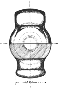
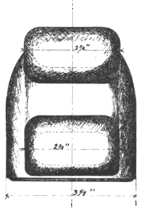
A special form of heavy, double petticoated glass insulator (see Figs. Nos. 4, 5 and 6), designed to hold two wires, with separate tie wires, supports the power circuits on the cross-arms in subways and on the elevated structure, and the special form of porcelain insulator employed is shown in Figs. 7 and 8.
 |
| Fig. 4. |
 |
| Fig. 5. |
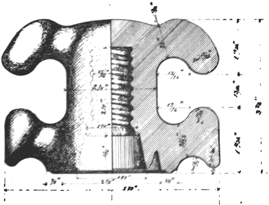 |
| Fig. 6. Heavy Two-Wire Glass Insulator |
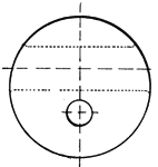 |
| Fig. 7. Porcelain Insulator |
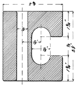 |
| Fig. 8. |
