[Trade Journal]
Publication: The Journal of Electricity, Power and Gas
San Francisco, CA, United States
vol. 13, no. 2, p. 148-150, col. 1-2
SPECIFICATIONS OF A PROPOSED INSULATOR PIN.
BY RALPH D. MERSHON.
NO general standard exists at present in the matter of insulator pins. As a result, there is often confusion and dissatisfaction in ordering and obtaining pins. This discussion of a proposed standard pin is intended to lead up to a general specification covering wooden pins, and, so far as it may, metal ones.
Theory --
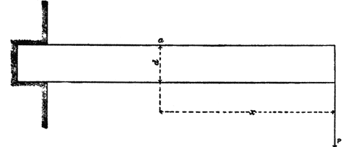
[too technical to reproduce]
 |
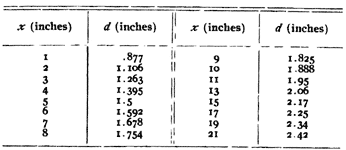 |
This table shows that for a pin having upon it a pull one inch above the cross arm, the diameter at the cross arm must be .877 inches; that one having a pull upon it ten inches above the cross arm must have a diameter at the cross arm of 1.88 inches, etc. +
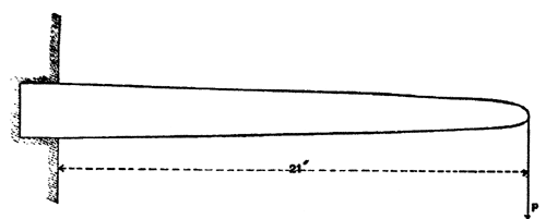 |
| Figure 2 |
Figure 2 is a sketch of such a theoretical pin drawn by platting the above values to a scale one-quarter of full size. Figure 2 represents all sizes of pins up to and including one the pull upon which is applied twenty-one inches above the cross arm. That is, if we want a theoretical six-inch pin we must cut six inches off the end of Figure 2 and use that; for a ten-inch pin we must cut off ten inches, etc.
The practical pin must be a modification of the theoretical pin. The end must be square and a portion of the small end must be threaded. The pin must also have a shoulder just above the cross arm. It will be noticed that, except near the end, the sides of the theoretical pin are practically straight. It will suffice, therefore, if in designing a pin we fix the diameter at the lower end of the thread portion and the diameter just above the cross arm and make the contour between these points a straight line.
Threaded End—It is proposed to make the diameter of the small end of the pin one inch; the length of the threaded portion two and one-half inches, and the diameter at the lower end of the threaded portion 1.25 inches, so that the threaded portion will taper from 1.25 inches to one inch in a length of two and one-half inches. The threaded portion of the insulator should have the same dimensions and taper as that of the pin.
Shoulder—It is proposed to make the shoulder 3/16 of an inch on all pins. That is, the diameter of the pin just above the cross arm will be 3/8 of an inch greater than the nominal diameter of that portion of the pin iti the cross arm; it is proposed to carry this diameter 1/4 of an inch above the cross arm before tapering the pin.
Dimensions in Cross Arm—It. is proposed to make the diameter of that portion of the pin in the cross arm, just below the shoulder. 1/32 of an inch less than the diameter of the hole in the cross arm, and at the lower end of the pin 1/16 of an inch less than the diameter of the hole in the cross arm. It is proposed, also, to designate this portion of the pin as having a nominal diameter equal to that of the hole in the cross arm into which the pin fits. Therefore, that portion of a pin which is to fit a one and one-half-inch hole in a cross arm will have a nominal diameter of one and one-half inch, but will have an actual diameter just below the shoulder of 1-13/32 inches, and at the lower end of the pin of 1-7/16 inches.
 |
| Figure 3 |
Thread—It is proposed to use on all pins a thread having a pitch of one-fourth inch or four threads to the inch, the form of thread to be that shown in Figure 3 (scale four times full size). As there shown, the angle between the faces of the thread is 90 degrees, and the top of the thread is flattened by cutting off, from the form the thread would have if not flattened, one-fourth its unflattened depth. The form of the thread in the insulator should be the same as that on the pin. If this is done it will insure the bearing surface being always on the sides of the threads and never on the edges.
Designation—It is proposed to designate that portion of the pin above the cross arm as the "stem" of the pin. That portion in the cross arm as the "shank " of the pin. It is proposed to designate a pin by the length of its stem, i. e., a pin whose stem is five inches long will be designated as a "five-inch" pin, one six inches long as a "six-inch" pin, etc.
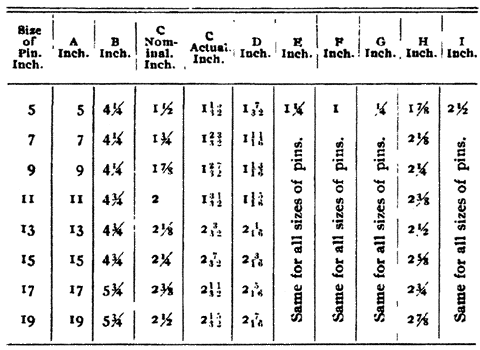
Dimensions of Standard Pins—In accordance with the above the following table has been prepared, giving a number of sizes of pins and their dimensions, which it is proposed to make standard. The diameter of the shank has in each case been fixed by making it approximately equal to (slightly larger than) the diameter of the theoretical pin corresponding to the length of the stem of the pin in question. The headings of the columns of the table refer to the lettering of Figure 4. Figure 4 is a full size unthreaded five-inch (proposed standard) pin.
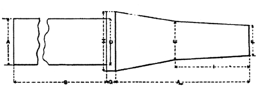 |
| Figure 4 |
 |
* For details of this installation and its performance see THE JOURNAL, Volume XII, page 110, June, 1902.
