[Trade Journal]
Publication: The Journal of Electricity, Power and Gas
San Francisco, CA, United States
vol. 13, no. 2, p. 145-146, col. 1-2
BURNING OF WOODEN PINS ON HIGH TENSION TRANSMISSION LINES.
BY C. C. CHESNEY.
IN this country it has been almost the uniform practice in high tension pole line construction to use wooden pins. The reason for their use has been the belief that because they were made of wood they strengthened the entire insulation of the pole line system, and were in consequence additional safeguards. These pins have generally been made of locust, oak or eucalyptus, and in order that the insulation might not deteriorate from the action of the weather, they have usually been treated carefully with hot asphaltum, paraffine or linseed oil. The temperature and character of the treating liquid have depended more or less upon the whim of the constructing or designing engineer. Although there has been no uniform method followed and although the materials used in the treatment have differed greatly, the results have been universally the same. Wood pins when used with glass or well vitrified porcelain insulators, have given very good service on potentials as high as 25,000 or 30,000 volts. There has been no unusual pin troubles at these voltages which could not readily be explained by porous or cracked insulators or by some peculiar climatic conditions. In my opinion, the success secured in the operation of the great majority of these lines is due to good insulation of the insulator, and the insulation of the pin has in reality contributed very little to that success. For 40,000 volts and for higher potentials, the insulators offered by all manufacturers do not have the same factors of safety as the insulators for lower voltages offered by the same manufacturers. The difference is not so much in the thickness or in the quality of the glass or porcelain used; it is more particularly in the general shape of the insulator and in the dimensions of the insulating surfaces and petticoats. For this reason, even under severe local surroundings, the 10,000-, 15,000-, 20,000-, or 30,000-volt insulators have shown very little surface leakage, and in consequence there has been comparatively little pin burning at these voltages. It is true that in localities of salt storms, of heavy sea fogs or chemical factories, there has been more or less pin-burning without regard to the type of insulator used, or to the potential of the system.
|
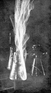
The writer has been informed that a certain plant using only 440 volts has at times great trouble from the burning of pins, although 10,000-volt insulators are used. This trouble is due entirely to the deposit on the insulators from a neighboring chemical factory, and as might be expected their period of no-burning is during the rainy season. These instances, however, are rare, and when the cause is apparent, the remedy is usually at hand. The pin burning on 40,000- and 50,000-volt lines is somewhat different. Eliminating all causes due to broken or defective insulators, the actual flow of current over the surfaces and through the body of the pin is probably very small. On the lines from which the writer has secured burned pins two used 11-inch Locke insulators, as shown in Figures 1 and 2; the third used the Redlands type. The first two lines were operated at a potential between 45,000 and 50,000 volts, and the third at about 33,000 volts. The pins shown were taken from perfect insulators and in some cases the insulators were immediately put back on the line. The pins shown in Figures 1 and 2 were made of eucalyptus and boiled in linseed oil. The line using the pin shown in Figure 2, also used a porcelain sleeve covering the base of the pin. Figure 3 shows the well-known Locke iron-pin with porcelain base and oak thread. In an exhibit of three pins, all of the type shown in Figure 1, these pins were taken from the same pole and occupied the relative positions as shown in the cuts and invariably the burnt sides stood towards the damp winds from the ocean. As other exhibits there may be shown burned pins of the type shown in Figure 2 as well as a Locke iron-pin with porcelain base, Figure 3, taken from a 33,000-volt line. The striking feature is the burning of the wooden thread to the iron pin. The writer has been informed by the general superintendent of this plant that every pin that has been examined on this line is burned in exactly the same way, yet there has been comparatively few punctured insulators and no cross-arms burned from the current leaking over the surface of the insulators. In a pin taken from a 50,000-volt line, the pin shown being sawed in sections, the noticable feature is that the burned section is entirely in the upper part of the pin about one and three-fourths inches below the thread. The outside surface and the center of the pin below this point shows no charring. It would appear that at least in this instance, the burned section was the point of highest resistance of the pin, and that the lower part of the pin was a good enough conductor to permit the small current- which leaked over the surface of the insulator to flow without any special generation of heat iu that section of the pin. The reduced insulation of the pin and insulator was no doubt due to the dust and fog. The upper portion of the pin, being better protected by the insulator from fog and dust, had in consequence higher surface resistance. A dark spot which appeared on the right hand edges of the lower section of this particular pin is the sap section of the wood which has been discolored by the linseed oil boiling which the pin originally had. This section has been in no way affected by the current. A peculiar action is occasionally found on high tension transmission lines, and for better name, has been called "digesting the thread of the pin." The thread of the pin softens while in service and may be rubbed off with the fingers. This soft wood has a sour taste and resembles digested wood pulp. This action is not necessarily accompanied by the burning of any portions of the pin.
The evidence here presented, while not conclusive, still points to the advisability of using iron pins with modern insulators properly chosen for the line potential.
 |
| Figure 1 |
 |
| Figure 2 |
 |
| Figure 3 |
* Abstract of a paper, advance copysubject to revisionof an "Introduction" to a discussion to take place at the regular meeting of the American Institute of Electrical Engineers to be held in New York City, March 27, 1903.
