[Trade Journal]
Publication: Electrical World
New York, NY, United States
vol. 27, no. 19, p. 532- 533, col. 1-2
The Folsom-Sacramento Power Transmission Plant.
The completion of the power transmission scheme between Folsom and Sacramento is the conclusion of a vast enterprise, undertaken in doubt and terminated in a success which has demonstrated not only the tremendous resources of the State of California but also the feasibility of electrical transmission over long distance commercially. A preliminary sketch of the progress of the work was given in our issue of April 6, 1895.
| |||
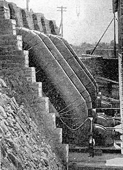
| "A" Penstocks and Turbines at Folsom. |
The dam is a massive structure of granite laid in Portland cement. It is 650 feet long, 89 feet high in the centre, 87 feet wide at the base, 25 feet wide at the crest, and contains about 48,590 cubic yards of solid masonry. It is provided with a heavy wooden shutter or flashboard 6 feet high which at high water is lowered into a recess in the crest of the dam. At low water this shutter is raised by hydraulic pistons, the depth of the basin is increased by 6 feet and additional storage capacity provided. Normally the dam forms a storage basin or reservoir miles tong, with a capacity of 13,000,000 cubic yards of water.
At each side of the dam are massive granite bulkheads and three head-gates operated by hydraulic machinery, each headgate 16 feet wide. The canal on the West Side, intended principally for irrigation, is not yet completed.
The total length of the East Side canal is 9500 feet. Section 1 is 53 feet wide on top and 45 on the bottom. Sections 2 and 3 are each 50 feet wide on top and 40 feet on the bottom. The depth is 8 feet. All the water passes through the State Power House through Leffel turbine wheels, developing some 800 horse-power, used for air compressors, electric the jurisdiction of the Folsom Water Power Company ceases, and that of r the Sacramento Electric & Power Company begins.
| |||
| Exciters and Governors in Dynamo Room at Folsom. |
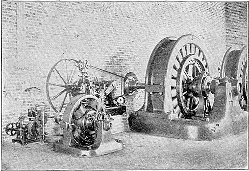
At the power house the canal makes a sharp turn at right angles and widens out into a forebay, 150 feet long, 100 feet wide and 12 feet deep, which forms a settling basin for debris. The hydraulic apparatus, manufactured by S. Morgan Smith, of York, Pa., consists of four pairs of 30-inch wheels of the McCormick horizontal-shaft turbine type, each pair of 1260-hp capacity at 300 revolutions operating under a head of 55 feet. The steel penstocks are 8 feet in diameter, and each wheel has two draft tubes. The governors are of the Faesch-Picard type, and these are assisted by heavy fly-wheels fitted to the water-wheel shafts. The hydraulic plant also includes two special horizontal wheels for the exciters. The water after having passed the turbines is discharged into a tail-race canal which will distribute water for irrigation over the country south and west of Folsom.
| |||
| Air Blast Equipment at Folsom. |
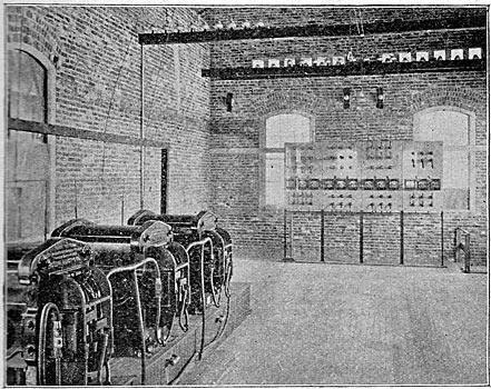
The power house is a two-story brick building. The water-wheels are placed in the open air between the forebay and the wall of the structure through which the turbine shafts pass. To each shaft is coupled a 750-kw (1000-hp) General Electric three-phase generator, the largest of their type yet constructed. Each is a 24-pole machine delivering current at 60 cycles 800 volts and running at 300 revolutions per minute. The exciters are 4-pole 500-volt 30-kw generators, either one of which is of sufficient capacity to excite the fields of all four generators. From the generators the current passes to the generator switchboard and thence to nine step-up transformers in the upper story of the power house. The capacity of each transformer is 250 kilowatts. They are cooled by an air blast from blowers driven by induction motors. In these transformers the pressure is raised from 800 volts to 11,000 volts and the current passes to the high-tension transmission lines carried out of the power house through porcelain-lined holes in the wall.
The switchboards are of Tennessee marble, and are so arranged that the generators may be run in parallel or on separate lines as may be desired. The generator switchboard carries the necessary switches, instruments and other apparatus for synchronizing the generators. The boards in the transformer room carry switches for the high and low tension sides of the transformers, and switches and current indicators for the transmission lines.
The pole line is double throughout, and follows the highroad from Folsom to Sacramento, a distance of 24 miles. Each pole carries two cross-arms for two circuits, each circuit consisting of three bare copper wires supported on double-petticoated porcelain insulators, especially designed and made for this installation at the porcelain factory of the General Electric Company at Schenectady. Each insulator before shipment was exposed to a test of not less than 25,000 volts, alternating. The loss is calculated to be 7.5 per cent. when transmitting 3000 horse-power.
The telephone line is carried on the same poles as the transmission line, and connects the power house with the sub-station in Sacramento. The transmission lines being spiraled every mile, and the telephone wire transposed every fifth pole, no induction is noticeable on the telephone circuits and conversation is not in any way interfered with.
The sub-station is a fireproof two-story brick building on the corner of Sixth and H Streets, Sacramento, having the transformers on the second floor and the dynamo room on the ground floor. In the transformer room the high-tension switchboards receive the terminals of the 10,000-volt lines and operate the different combinations of the step-down transformers. These transformers, also ventilated by blowers, vary in size according to the duty required of them, the secondaries delivering current at 125, 500 and 1000 volts. They number twenty-one 15 of 125 kilowatts and 6 of 40 kilowatts.
| |||
| Step-Up Transformers and Outgoing Wires at Folsom. |
| |||
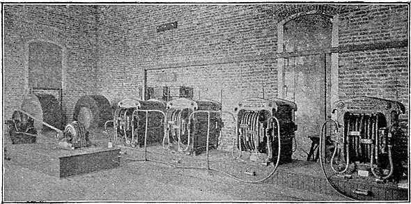
| Step-Down Transformers at Sacramento. |
The transformers are connected to high and low-tension switches on the boards, and from these the current passes to the distributing boards for the synchronous motors, power circuits and incandescent lighting.
In the main or dynamo room of the substation a line shaft runs the entire length. To this are directly coupled, through friction clutches, three synchronous motors, each of 250-kw capacity, wound for a potential of 500 volts and run at a speed of 450 revolutions. To the line shaft are belted one 200-kw and one 90-kw multipolar General Electric railway generators and two 100-kw Edison bipolar machines, all of 500 volts, and three 100-light and two 75-light Brush arc machines.
In this room are also the switchboards for controlling the synchronous motors, the railway generators and circuits and the arc dynamos.
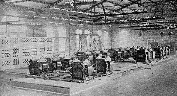
| |||
| Dynamo Room Sub-Station at Sacramento. |
The insulators use were General Electric dry process porcelain U-744.or the operation of the synchronous motors 750 kilowatts of transformer capacity is utilized, the balance being used for low and high-tension distribution. The low-tension current is distributed by a three-phase four-wire system, combining the three-phase and Edison three-wire systems, i.e., three wires for the three-phase current and a fourth or neutral wire. Incandescent lights are connected between the neutral and any one of the three other wires, while motors are connected to the three-phase wires, giving at the mains 115 volts for lamps and 200 volts for rotors. The feeders for this extensive system pass from the sub-station trough a distributing switchboard, which carries potential regulators for maintaining constant pressure at the mains. Additional circuits run from the sub-station at 500 and 1000 volts, supplying current for lights and motors in the more distant parts of the city.
Power was transmitted for the first time from Folsom to Sacramento, on July 14, 1895, for the operation of the Sacramento Street Railway. The power transmitted is now being used for manufacturing purposes, as well as for lighting the city and running the street railway. Among the establishments now using the power are flour mills, box factories, machine shops and hotels.
The entire equipment was carried out by the General Electric Company whose apparatus is exclusively employed.
This plant is a complete illustration of the possibilities of electric transmission, every problem to be met with in transmitting power over long distances at high potentials and utilizing it having been solved successfully.
