[Trade Journal]
Publication: Electrical World
New York, NY, United States
vol. 25, no. 14, p. 433-434, col. 1-2
The Sacramento-Folsom Power Transmission Plant.
The perfection of a system, by means of which power may be economically transmitted over long distances, and which suddenly broadened the field of critical effort, is now receiving practical and successful illustration in many places in this country, and our readers are familiar through our columns with the excellent work done at Taftsville, Conn.; Concord, N. H.; Hartford, Conn.; Columbia, S. C., and elsewhere. One of the best and most recent examples and one of the most interesting is the plant, nearly completed, which the Sacramento Electric Light & Power Company is constructing at Folsom, on the America River. where one of the largest water powers in California will be utilized. It is the more interesting in that the scope of the scheme. which at the commencement of the hydraulic work in 1866 was limited in its range, has been almost inconceivably widened by the alliance between water power and electricity which modern invention has brought about.
| |||
| Gate Mechanism. |
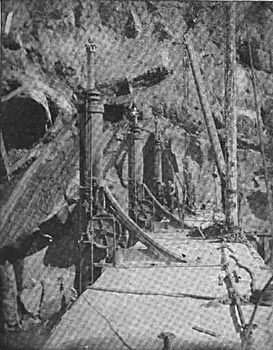
The work as at first conceived embraced a dam across the American River, near Folsom, and the utilization of the water, primarily for power purposes, and secondarily for the irrigation of the surrounding country. The plan was modest in its proportions, and remained so for many years, but the introduction of electricity immediately magnified it into a grand scheme contemplating the utilisation of about 5,000 hp for transmission purposes, and 1,200 hp for use in the state prison located by the side of a special state power house.
The first step was taken in 1866 when the foundation for the dam was laid. Some years later the California state government contracted with the power company, and In exchange for water power privileges and certain grants of land for prison buildings, agreed to supply convict labor. In 1888 a new contract was effected, the size of the dam and canals as indicated in the original plans were greatly increased, and under these new plans the work, pushed forward vigorously, is now rapidly nearing completion. The dam is a massive structure of granite laid with Portland cement. It is 660 feet long, 89 feet high in the centre, 87 feet wide at the base. 25 feet wide in the crest, and contains about 48,590 cubic 3 yards of solid masonry. It is provided with a heavy wooden shutter or flashboard six feet high, which at high water is lowered into a recess in the crest of the dam.
| |||
| View of Dam From Below. |
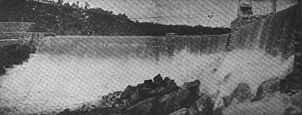
At each side of the dam is a massive granite bulkhead, in which ate three head gates operated by hydraulic machinery, each head-gate being 16 feet wide. The West Side Canal is not yet completed, but is designed to be 40 feet wide at the top, 30 feet wide at the bottom, and six feet deep. it is intended principally for irrigation purposes.
The East Side Canal is completed from the dam to the site of the power house, a distance of about two miles. It is 50 feet wide at the top, 40 feet wide at the bottom, and 8 feet deep, having capacity of about 87,000 cubic feet of water per minute. The canal is divided into three sections and follows the bank of the Liver for about two miles. It is constructed partly of masonry, partly formed by cuts in solid rock, and partly by earth cuts and fills. Just before it reaches the power house of the Sacramento Electric Light & Power Company it has been widened into an immense basin to hold the logs of the America River Land & Lumber Company, which company is about to erect at this point large saw mill, to be operated entirely by electricity.
The power house of the Sacramento Electric Light & Power Company is situated at the extreme end of the canal on the west side of Folsom, where a fall of 55 feet is available at high water. Here an immense cut in solid rock Ins been made about 60 feet deep, 100 feet wide, and 150 feet long, from which a channel 40 feet wide leads to the river. In this cut the foundations for the machinery and the granite walls, piers and arches of a two-story building have already been laid, and the structure is progressing rapidly. At the power house the canal makes a sharp turn at right angles and widens out into a fore bay 150 feet long. 100 feet wide and 12 feet deep, forming a settling basin for debris. It is divided into two distinct parts by a wall provided with suitable gates so that one aide may be cleaned out while the other is in operation. Prom the lower end of each section of the fore-bay a sluicing canal, normally closed by gates, leads to the lower river, and through this the sand and debris will be carried away and kept from the wheels, The contract for the entire mechanical and electrical equipment was awarded to the General Electric Company in September, 1894. The contract for the hydraulic apparatus was let to the S. Morgan Smith Water Wheel Company. This apparatus will consist of four pairs of McCormick horizontal-shaft turbine wheels, enclosed in steel cases having steel inlet pipes eight feet in diameter and double discharge tubes. The governors used will be of the Faesch-Picard type, and will be supplemented by heavy fly-wheels on the water wheel shaft. Each pair of wheels will have a capacity of 1,260 hp at 300 revolutions per minute. They embody all that is latest and moat improved in hydraulic practice, and are of larger capacity than any hitherto constructed in this country, with one exception. They will be operated under a head of 55 feet. The hydraulic plant also includes two special horizontal wheels for the exciter. The water after having passed the turbines will be discharged through tunnels under the power house into irrigation canals lot distribution over the country south and east of Folsom.
The generators will be four in number, and of the General Electric three-phase alternating current type, furnishing current at 800 volts potential. The armature shafts will be directly connected to the shafts of the wheels by means of flange couplings. Each generator will have a capacity of 1,000 hp, and will weigh about 30 tons. They will be the largest three-phase generators yet constructed. The wheels and generators will be located on the first floor of the building 16 feet above the level of the water in the tail race, but will not occupy the same room. Between the wheel room and the generator room a heavy masonry wall has been built. The openings through which the turbine shafts will pass will be small, and the wall will serve to protect the electrical machinery from the possible entrance of water. The water wheel regulators will be in the dynamo room, and the operator will thus have full control of the hydraulic machinery while in sight of the electrical instruments on the switchboard. Both dynamo room and wheel room will be provided with traveling cranes.
| |||
| View From Above Dam. |
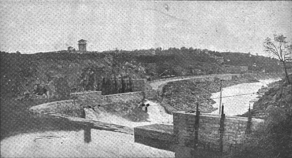
In the second story of the power house directly over the dynamo room, sub-station step-up transformers will be installed, of the standard type used by the General Electric Company in such plants. In these transformers the E. M. F. will be raised to 11,000 volts, and connections to the line will be made through marble switchboards equipped with the necessary switches and fuses.
Special provision to prevent shut-down by accident or unforeseen contingency has been made in the pole line, which will be in duplicate from the Folsom power house to the Sacramento transformer sub-station, and will run along the line of the Sacramento & Placerville Railways as far as the city. For this purpose 2,600 40-foot round cedar poles, 16 inches in diameter at the butt, are used, and each will carry two cross-arms for the two circuits. Each circuit will consist of three bare copper wires supported on double-petticoat porcelain insulators especially designed and made for this installation at the porcelain factory of the General Electric Company, at Schenectady. Each insulator is subjected before shipment to a test of not less than 25,000 volts, alternating current. Each three-wire circuit can carry the output of one dynamo, and any dynamo can be thrown on any line, though they will all be normally operated in multiple. The sub-station at the end of the transmission line will be a fireproof two-story brick building, divided into four parts, namely, the step-down transformer room, the motor, railway and arc dynamo room, the shop and testing room and the store room.
In the transformer room transformer switchboards will receive the terminals of the 10,000-volt transmission lines and enable the attendant to operate different combinations of the transformers. The step-down transformers, of the air-blast type, wilt vary in size according to the duty required of them, and deliver current at the secondaries at 125, 250, 500, 1,000 and 2,000 volts for incandescent lighting and motor service. In the main room will be three 300-bp three-phase synchronous motors of the standard General Electric type, directly connected to a line shaft. This shaft will be provided with clutch pulleys to drive several 500-volt continuous-current railway generators and a number of arc dynamos.
The incandescent lighting, commercial arc lighting and stationary motor work in the central portion of the city will be handled by a low tension modified Edison three-wire system, feeders from the secondaries of the step-down transformers supplying current to a network of mains. The motors will be of the three-phase induction type, and can be connected to the mains at any point. The street and private arc lighting will be done on the constant current series system, while outlying motors will be operated from higher potential lines with individual transformer reduction, or will be high potential synchronous motors.
