[Trade Journal]
Publication: Electrical World and Engineer
New York, NY, United States
vol. 37, no. 13, p. 503-508, col. 1-2
Power Transmission in Utah.
RESULTS AND LESSONS FROM THE OPERATION OF THE LONG-DISTANCE
POWER TRANSMISSION AND DISTRIBUTION SYSTEMS OF
THE UTAH LIGHT & POWER COMPANY.
BY J. R. CRAVATH.
THE various transmission plants and the distribution systems of the Utah Light & Power Company in and near the cities of Salt Lake and Ogden, Utah, are among the oldest and most important of their kind, and much can be learned from the experience of this company which is of value to those about to undertake long-distance transmission and distribution from water powers as well as from more recently installed transmission plants. For the many practical points here given as to the working of this company's system, acknowledgment is due to the kindness of R. F. Hayward, chief engineer of this company and consulting engineer for numerous other plants in Utah. Mr. Hayward's extensive experience, covering six years in this work, and his opportunities for observation, constitute him an authority on this branch of electrical engineering, and the readers of this article will appreciate the professional courtesy which has prompted him to furnish such complete information on a class of subjects about which none too much is generally known.
The system of the Utah Light & Power Company comprises three water-power plants, several high-tension transmission lines, and also light and power distribution apparatus in and near Salt Lake City and Ogden, Utah, together with one sub-station for supplying the Salt Lake City Railroad, and some reserve steam plants. Probably in no other city of its size in the United States has electrically transmitted power reached such a relatively important place in the community as at Salt Lake City. The development not only started early, but has been very rapid. The snow-fed mountain streams of the Wasatch Range, to the east of the Salt Lake Valley, offered opportunities to the hydraulic and electrical engineer which were not neglected. To understand the situation a short historical review will be necessary. Although coal is not excessively high, being from $2 a ton for slack to $4.50 for best lump, the proximity of water-power with high head to such a market as Salt Lake City and its surrounding smelters and other power consuming industries led to the erection several years ago of three different water-power plants by three different companies. The Big Cottonwood Power Company completed a plant in the Big Cottonwood Canon, 14 miles southeast of Salt Lake City in June, 1896. The Pioneer Electric Power Company started its plant in the Ogden Canon near Ogden, 37 miles from Salt Lake City in July, 1897. The Utah Power Company in 1897 built a plant in the Big Cottonwood Canon for transmitting power for the Salt Lake City Railroad. These three plants finally became consolidated with the electric lighting interests of Salt Lake City, and are now operated as parts of one complete and comprehensive system, owned by the Utah Light & Power Company, covering a district extending north and south about 6o miles, including Ogden, Salt Lake City, and a district 13 miles south of the latter place, including some large smelters. The accompanying map (Fig. I) shows the district covered and the lines and power houses.
 |
| Fig. 1. - System of Utah Light & Power Company. |
A brief review of the equipment and location of the three waterpower stations will be necessary to a full understanding of the situation.
POWER HOUSE EQUIPMENT.
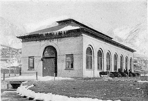
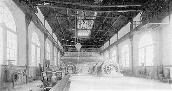
The plant at Ogden gets its water from the Ogden Canon, a narrow gorge about 6 miles long (see map, Fig. 1), through which a stream flows, draining a rather large area of high ground. At the head of the canon is a level valley 4 by 5 miles, which would make a good storage reservoir. At present, however, there is a dam 300 ft. wide and 20 ft. high across the cation, making a 5-acre reservoir. From this reservoir the water is drawn through two 5-ft. gates into a massive concrete tower, from which it flows in a pipe 6 ft. in diameter, 6 miles to the power house. Five miles of this pipe is wooden stave, and the last mile is steel, taking the water from the wooden pipe at 100-ft. head and delivering it at 450-ft. head. At the power house the pipe line divides into two 6-ft. diameter receivers, one along each side of the building, with 2-ft. delivery pipes running into the power house for each water wheel. This power house (see Figs. 2 and 3), is designed for 10 generators of 750 kilowatts, each direct connected to a waterwheel. Five of these have been put in. The waterwheels are the Knight impulse pattern, running at 300 r. p. m., and have Knight automatic electric relay governors. The generators are General Electric 60-cycle, three-phase, revolving armature, 750-kw machines, generating at 2300 volts. The exciters are two 500-volt, 100-kw generators direct connected to waterwheels. A Venturi watermeter is placed in each receiver just outside the power house, so that the water consumption can be measured continuously. The distribution in Ogden is direct from this station at 2300 volts. For transmission to Salt Lake City there are nine 250-kw air-blast transformers arranged in delta connection, stepping up to 16,000 volts. The transmission line is 36-1/2 miles long, and consists of two circuits of three No. 1 bare hard-drawn copper wires on the same pole line. The insulators are porcelain. The poles are from 35 to 50 ft. long. For 16 miles the pole line is just outside a railroad right of way, and the rest of the distance passes over open country.
| |||
| Fig. 2. - Exterior of Ogden Power House. |
The Big Cottonwood plant, which is southeast of Salt Lake City in the Big Cottonwood Canon, leads its water from a small reservoir through a 4-ft. steel pipe line, which passes first through a tunnel 500 ft. long, and then down a steep slope to the power house. The pipe line is 1800 ft. long and the head is 380 ft. The receiver at the power house is the same diameter as the pipe line. There are four 600-hp Felton waterwheels running 300 r. p. m., each with two nozzles. One nozzle is opened and closed by a gate valve, the other has a hood operated from a lever in front of the switchboard for regulation. The regulation is all done by hand. The generators are General Electric, 60-cycle, 500-volt, three-phase, 450-kw. There are two exciters separately driven by waterwheels. On the upper floor of the power house are six 250-kw transformers, air cooled, stepping up from 500 to 10,000 volts. The transmission line to Salt Lake City consists of two three-phase circuits of No. 2 wire (see Fig. 1), 14 miles long, part over rough, mountainous country and part along a country road. Porcelain insulators are used. Part of the distance these circuits are now run on the same poles as the line from the Utah station.
| |||
| Fig. 3. - Interior of Ogden Power House. |
The Utah station is also located in the Big Cottonwood Canon, and gets its water from a small wooden dam just below the tail race of the other station. For 1-3/4 miles the water is taken in a wooden flume 4 ft. wide by 3 ft. deep, and is then delivered to a steel pipe 4 ft. diameter, and giving a head of 450 ft. The power house has two 1000-hp Pelton waterwheels running 300 r. p. m., direct connected to 750-kw, two-phase, 60-cycle, 500-volt Westinghouse generators. Exciters are independently driven. The main waterwheels are regulated by a Replogle relay governor, acting on a throttle valve. Step-up phase-changing transformers raise the voltage from 500 volts, two-phase to 11,000 volts, three-phase. The transmission line has two three-phase circuits of No. 3 bare copper wires on porcelain insulators, and is about 12 miles long. This station is operated in parallel with one generator in the Big Cottonwood plant to supply the Salt Lake City Railroad through a sub-station near the middle of the city.
The railway sub-station just mentioned has two two-phase, 300-kw rotary converters supplied from step-down transformers. One of the rotaries is usually sufficient to carry the load. The paralleling is, of course, necessarily done on the three-phase high-tension lines.
The light and power distribution at Salt Lake City is accomplished through the medium of another sub-station near the middle of the city. Here the high tension lines are run in from both the Ogden and Big Cottonwood plants. Both are stepped down to 2300 volts, and the 2300-volt lines are thrown in parallel, thus putting the Ogden and Big Cottonwood plants in parallel through the medium of the 2300-volt secondaries.
DISTRIBUTION.
It has been Mr. Hayward's aim, ever since the consolidation of interests made it possible, to bring everything under one uniform simple scheme of generators and distribution. Fortunately the frequency of all the plants was the same (60 cycles), but there the uniformity ended. As the- secondary system is now uniform, so that the plants can be operated in parallel, the difference in transmission voltage is no great inconvenience save as it necessitates greater reserve capacity in transformers at the sub-station, and prohibits paralleling high-tension lines. However, it is contemplated to raise the transmission line voltage on both the Ogden and Big Cottonwood lines to about 24,000. This can be done on the Ogden line without rewinding transformers by changing from the delta to the Y method of connection. The Big Cottonwood transformers will have to be rewound. From the light and power sub-station a network of 2300-volt mains is fed. This network is shown in Fig. 4. The primaries of the street transformers are connected delta-fashion, but the secondaries are on Y-connection. When motors under 10 horse-power are to be run they are connected between the outside legs of the Y, which give zoo volts. Motors over 50 horse-power are put on separate transformers. The lights are balanced between the outside legs and the neutral on 115 volts. This makes a very satisfactory scheme of distribution. Six transformers are placed to a block, at opposite corners, and they feed into secondary mains running around the block. Adjacent blocks are tied together through fuses, so that the secondary system in the down-town district is also a complete network. This secondary network is shown in Fig. 5. In the residence district two secondary wires (a leg and a neutral) are first run down a street, balancing one street against another, and as customers increase the third and fourth wires are put in and connection is made with adjacent secondary systems, everything working toward the network idea. Mr. Hayward believes in network and parallel running throughout, as the only ways to secure reliability of service and minimum voltage variations.
 |
| Figs. 4 and 5. -Distribution System, Salt Lake City. |
At the sub-station there is a small steam plant in reserve which it is expected to increase as the system grows, to reduce as far as possible the chances for interruption of service. There is also an old electric light station near the sub-station which can be run in case of emergency. At present there are in this latter station some synchronous motors driving series arc-light machines. These motors can be run as generators on short notice. It is expected in time to replace all series continuous-current arcs with constant-potential alternating arcs. The series-alternating arc is not liked, because of the complications in the way of high-tension circuits on pole lines which it involves. It is desired to keep the circuits as few and simple and safe as possible. On all pole lines carrying 2000-volt mains, the inner wires between which linemen must climb are at the same potential, and everything possible is done to make it safe for linemen in their dangerous duties. In case constant-potential alternating arcs are run for street lighting, a magnetic switch will probably be used by which all the lights on a section of street can be turned on at once by an inspector. About 500 constant potential alternating commercial arcs are in use in Salt Lake and Ogden.
In order to bring the voltage right on the 2300-volt mains in both Salt Lake City and Ogden and allow for line loss between Ogden and Salt Lake, the step-up transformers on the Ogden line are wound 7 to 1 and 6 to 1 on the step-down. A certain degree of regulation at Salt Lake can be obtained by varying the exciter motors driving arc-light machinery. With heavy load on the line, a variation of 10 per cent can be obtained in this way. Regulation of voltage at Salt Lake City is also obtained by varying the exciting current at the Big Cottonwood generators. As explained elswehere, the waterwheels at the Big Cottonwood plant have no automatic regulators. Those at the Ogden power house have. The hand regulators at the Big Cottonwood power house are, therefore, left untouched, so that they supply constant power, and the variations in demand are taken up by the governors at Ogden. But the exciting current on the Ogden generators is maintained nearly constant, except that such adjustment as necessary is made to regulate the voltage on the Ogden distributing circuits. If the Salt Lake City voltage is to be raised, the Big Cottonwood generators have their fields strengthened. The regulation is controlled by telephone from the Salt Lake sub-station.
It is of value to note the ease with which the different stations having types of alternators are run in parallel. At light loads there is a slight interchange of current between the two stations sometimes, but at heavy loads all these induction and resonance effects are drowned out.
SWITCHBOARD CHANGES.
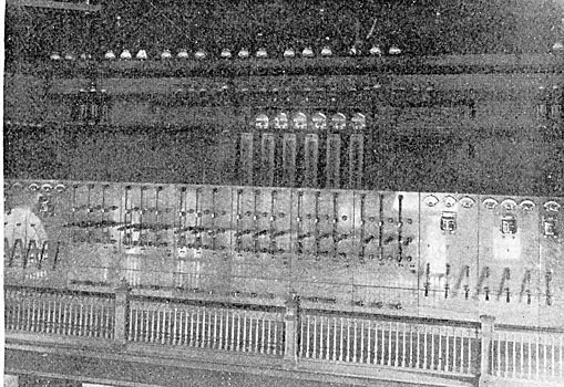
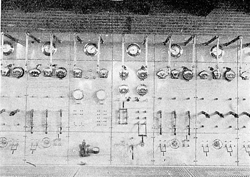
All of the power houses were originally built with the transformers and transformer switching arrangements on a different floor from the generators and generator switchboard. Under the circumstances, this is an undesirable arrangement. In the Big Cottonwood and Ogden plants, the transformer switches will be moved down onto the main floor where they can be got at quickly by the men attending the waterwheels and generators. Both economy of labor and reliability of service demand this. The high-tension 16,000-volt switchboard at the Ogden plant, as it is at present, is shown in Fig. 6. The low-tension 2300-volt board is shown in Fig. 7.
WATER SUPPLY.
The securing of a reliable supply of water is the cause of much thought and anxiety in connection with an enterprise of this kind. Of course, with several different plants, the liability to interruption decreases, but the experience in Utah as well as elsewhere shows that the constancy of water supply is something about which little was known when the first plants were built. In Utah, where the power houses are located in canons from 4000 to 5000 ft. above the sea, where the temperature reaches 40 degs. Fahr. at times, and where the snow falls heavily in places there is a constant menace to water power plants from snowslides and ice dams, this being the more serious because of the small actual volume of water in the streams. In the Big Cottonwood Canon, for example, two or three snowslides may be expected each year, which will dam the stream partially for 20 hours. On the other hand, in the dry season, the irrigation, which has the right of way over everything demands the entire flow of the stream. For these reasons it is important both for power and irrigation to construct large reservoirs for storage of water. This more easily said than done in some of these Wasatch canons, owing to the difficulty of finding bed rock. A large storage dam contemplated for the Ogden plant was never built because of the great depth of bed rock upon which to found it. To provide for irrigation and allow water to be used with economy at Ogden a storage reservoir has been built below the plant so that water need not be wasted by the plant to provide irrigation, as had at first to be done. It is, of course, desirable to have storage reservoirs away from the current of the main stream to prevent them filling up with boulders in flood seasons, but so far the construction of such reservoirs has not been possible for these plants.
The load has had a remarkable growth. That at Ogden, for example, has doubled in two years. Plans are under way for the enlargement of the water storage capacity in both the Ogden and Big Cottonwood Canons. The great depth of bed rock has made worthless many of the original plans for storing water. Unless a dam is sunk to bed rock there is an immense amount of leakage. In the Ogden Canon the plan is to build four low inexpensive dams, as shown by the accompanying map, farther up the river than the originally proposed dam. These will give within 25 per cent of as much water as the one big dam originally contemplated, and cost far less. The locations of these proposed dams are shown in Fig. 5.
At Ogden, where the velocity of the water around the intake is slow, owing to the volume of standing water at that point, there is little trouble with ice around the screens, but in the Cottonwood Canon, where there is a temporary intake and high velocity of water, there is trouble with ice forming on the screens. The reservoir originally constructed for the Big Cottonwood plant could not be used, because of its porosity, but a concrete dam is contemplated, which will give a good intake.
In regard to methods of conveying water the open flume has proven rather unsatisfactory for use around these steep canons, where falling rocks or snowslides are liable to carry away the whole structure that happens to lie in their path, and cut off the supply of water completely. The "Utah" plant of this company is supplied through a flume, which several times has been broken by falling rocks so that the plant had to shut down until repairs were made. Mr. Hayward believes in general that if the development of a water power is so expensive in proportion to the power produced that the cheapest construction must be chosen on account of its cheapness, the water power is not worth developing. Reliability is essential to the success of every power-transmission scheme, and any pipe line or flume for conveying water to the plant should be thoroughly ' protected from snow and landslides, and a tunnel or buried pipe line will often be found more economical than a flume or ditch. Mr. Hayward finds that the examination of smooth, gentle slopes at the foot of cliffs shows that these smooth places are frequently caused by snowslides, and are places to be avoided, and in such cases nothing but a buried pipe line or flume heavily timbered over the top should be used.
One of the largest wooden pipe lines ever built is that at the Ogden plant. It is 6 ft. diameter outside and 5 miles long. It is laid in an earth-and-rock cut on the south side of the Ogden Canon. Unlike many pipe lines it was not laid to hydraulic grade, but drops below the level of the intake in some places as much as moo ft. For protection from falling rocks a shed of 8-inch by 8-inch timbers covered with 3-inch planking has been built over the pipe most of its length. The shed has an angle of 20 to 30 degs. to the horizontal. It has saved the pipe many times, but has frequently to be repaired, as a result of this duty. Once by falling rocks (on one of the innocent-looking smooth slopes previously mentioned) two staves on the upper side of the pipe were damaged, but not sufficiently to necessitate shutting down the plant until several hours later, when it was convenient. A patrol is kept constantly on the pipe line. Blow-off valves to take out sediment during 'flood seasons are put at the low points in the pipe line, and air valves put at the high points. Just before the pipe line becomes covered with snow in winter there is some liability of these valves freezing, but after the snow comes there is no trouble. No ice forms inside the pipe even in the coldest weather.
The use of two receivers at the power house, as at Ogden, instead of one is emphatically recommended after experience with both plans.
The Venturi watermeters in the supply pipes at the Ogden plant have given some very valuable practical results in the operation of the plant. Economy of water is quite an object in this plant, because of the limited supply. Formerly it was the practice to run more generators than were necessary, and run them underloaded much of the time. After records began to be kept of the output in kilowatt-hours as compared with the mechanical horse-power of the water delivered by the wheels, the calculated efficiency obtained from the wheels in every-day running was raised from 38 per cent to 60 per cent. The men in charge of the station are held responsible for the efficiency, and they see to it that machines are not run underloaded. While the figures given may not be absolutely accurate, they are probably relatively accurate, which is all that is necessary under the circumstances. The plant is now carrying 600-kilowatts more load than formerly, and using no more water.
WATERWHEEL REGULATION.
In the matter of waterwheel regulation, which is a bugbear in many water plants, the results attained seem to be fairly good. The variable load is, however, but a small per cent of the total, except the railway load, and the supply pipes are large for the load that is being carried. As said before, there are no automatic regulators at the Big Cottonwood plant, but it is run in multiple with the other stations, which have automatic regulators on the waterwheels and consequently they furnish all the regulation. In the case of the railway load the variation in speed does not exceed 2 per cent on the waterwheels in the Utah plant, which furnish the regulation. Replogle governors are employed at this plant.
SWITCHING.
The switchboards at all the plants and at the sub-station have double sets of bus-bars and double-throw switches all through on both high and low-tension sides of transformers, on generators and on feeders, so that flexibility and reliability is assured as to switching arrangements. Figs. 6 and 7 show the Ogden switchboards. One peculiarity of this company's system, as at present operated, lies in the absence of fuses save on the street transformers and secondary distribution. Many other Western transmission plants have adopted the same practice. There are no fuses at the power house in the high-tension transmission circuits or on the 2300-volt street network, save at transformers. Mr. Hayward considers the blowing of a fuse without cause on a large system of this kind as too likely to cause serious results in the way of a general shut down for a few moments to be worth the risking. Of course, an alternating current system distributing current to rotaries, synchronous motors and large induction motors is not a pleasant thing to shut down, even for five seconds, and with everything in parallel on a network, the blowing of one fuse usually means the blowing of many more. When a short circuit occurs, it will usually burn itself off. If it is caused by an arc across the high-tension transmission lines, which occurs when something is thrown across the lines, the voltage will usually be pulled down enough to quickly break the arc.
| |||
| Fig. 6. - High-Tension Switchboard, Ogden. |
| |||
| Fig. 7. - 2300-Volt Switchboard, Ogden. |
The throwing of stations in parallel is accomplished preferably at one of the generating stations, or it may be done at the substation in Salt Lake City. Both stations are started on independent bus-bars, the synchronizer is put between the bars, and with the aid of the telephone which connects all stations, the speed of the two plants can soon be brought near enough so that they can be thrown together. Once together, they stay so without the slightest difficulty.
Both air-blast and oil-cooled transformers have proven very satisfactory on the high-tension transmission work. On the 2300-volt network on the street, the oil-insulated transformers have shown themselves so far to be much more reliable than the dry. No oil-insulated 2300-volt transformers have been burned out in two years, save a couple which accidentally carried twice full-load for a time while two or three dry transformers usually go out each lightning storm on the 2300-volt circuits.
RELIABILITY OF HIGH-TENSION LINES.
The service over the 16,000-volt high-tension line, 36-1/2 miles long, between Ogden and Salt Lake City, has been remarkably free from interruptions, the record from October, 1897, to December, 1900, being as follows : On one occasion a hurricane which tore up things generally through the valley broke down some telephone wires across the high-tension lines, but did not break poles or wires. On three occasions boys threw sticks or weeds across the lines, causing an arc between wires and a momentary short circuit. On one occasion an insulator was shot off. The Big Cottonwood and Utah lines have not been so free from interruption. The fact must be faced that wherever lines run through populated districts as they do in this case, there will be some trouble from the throwing of things across the lines and shooting at insulators. While this can be stopped to a great extent by offering rewards for offenders, and the emphasizing of the seriousness of the offense by the company, still such things will occasionally be done.
Mr. Hayward considers that building a transmission line without duplicate circuits so that repairs cannot be made on one dead line while the other is alive so that all will be dependent on the continuity of one line, is a practice that cannot be too strongly condemned. He believes that if a transmission line for supplying a large community will pay at all it will pay to put it in duplicate. Although repairs have been made on the Ogden 16,000-volt line while live, he does not consider it good practice.
In building a long-distance line of this kind over mountainous country, it is considered that No. 5, or better, No. 4, is the smallest wire that should be put up, for reasons of mechanical strength, and the transmission voltage need not be higher than will transmit the power over this size line with 10 per cent drop, as it is thought that a scheme that will not stand this loss is not worth working out. When these things are considered the necessity for exceedingly high voltages in many plants is not apparent. This company has some solid aluminum wire on a 6-mile line from the Utah plant to some smelters south of Salt Lake City, consisting of three No. 2 aluminum wires. This wire was ordered specially soft and was not stretched very tight, and the results have been perfectly satisfactory. A neighboring transmission line (the Provo) has found it advisable to replace some solid aluminum conductors with stranded aluminum, owing to the brittle hard spots in the solid single conductor.
While it has been the practice with most transmission lines so far constructed to run them as straight as possible across the mountains to save distance, Mr. Hayward is decidedly of the opinion that this is a mistake where accessibility is sacrificed for straightness. A line upon which much is depending must be patroled and accessible for repair, and it is better to go a few extra miles if necessary to secure these things rather than put the pole line where it is a laborious task to get at it in summer, and next to an impossibility in winter.
COST OF POLE LINES.
The cost of a pole line suitable for a transmission of this kind is a matter of considerable interest. The cost of the Ogden transmission line is given as approximately $2,500 per mile. This has six No. 1 wires, on porcelain insulators, and is on poles set 50 to the mile. The poles are mostly 35 ft., except in Salt Lake City, where they are 50 ft. Attention is called to the fact that the pole line, independent of the copper, is such a large proportion of the expense that an increase in voltage to reduce the copper required would not proportionately reduce the total expense, and in many cases would put a practical limit to the desirability of increasing the voltage. For example, it is figured that the copper on the Ogden line did not cost more than $1,000 per mile, and that, therefore, if an increase in voltage could have halved the copper required, the cost of the line would have been reduced only to $2,000 per mile, provided there was no extra expense for insulators, etc., due to the increase in voltage.
POLES.
The poles on this company's lines come from Northern Idaho. They are straight and slightly tapering. None are used less than 8-inch diameter at the top. The 35-ft. pole makes the stiffest cross-country pole line, but it is found that in the Utah bench lands, consisting of sand and gravel, it does not take many years for the pole to rot away just below ground; and if 40-ft. poles are used they can be cut off close to the ground when rotten and the poles set 5 ft. lower. It may prove a good investment to put cement around poles in this soil. Experiments are being made with it. It has been put 14 inches thick for a depth of 2-1/2 ft. around some poles in a specially bad spot at a cost of 80 cents per pole. Fifty poles to the mile is the minimum number that should be set, according to the experience in this country.
INSULATORS.
The insulators on the Big Cottonwood line were among the first high-tension insulators turned out and were made by the dry process. Fully one-third of them have had to be replaced. The insulators on the Ogden line were made by the Imperial Porcelain Works, and tested to 50,000 volts, as were those on the Utah line. Mr. Hayward reports no breakdowns of insulators on either of these lines. On the Cottonwood line it has never been found that a punctured insulator will cause a direct short circuit. If the insulator punctures, a small arc is formed from the porcelain into the pin, and the pin is gradually burned away until finally it breaks off if not attended to. It is the breaking of the pin and crossing of the wires that causes the trouble on the line, and not the original puncture. There is no instance of a pin being charred where the insulator was not punctured, which shows that up to 16,000 volts at least there is no burning of pins due to leakage over the surface of insulators, as has sometimes been supposed. As elsewhere, difficulty has been experienced with boys shooting at insulators with rifles, and, in fact, this is the most serious problem at the present time.
In one instance, where a boy threw a stick across the wires, a wire was burned off and fell to the ground. The power was interrupted while the wire was burning off, which lasted a few seconds, but after it fell to the ground things went on as if nothing had happened. Of course, this would not have been possible had any portion of the circuit been grounded permanently.
The wires on the Ogden circuit are transposed every half mile in a 50-ft. span, which is found to be a good plan, as it throws little side strain on the insulators, and it is not necessary to dead end the wires.
MISCELLANEOUS TRANSMISSION-LINE NOTES.
In making repairs on high-tension lines the circuit to be worked on is cut out, grounded and short circuited to prevent all danger from crosses with live lines while the men are working. The telephone is considered indispensable in the operation of a system of this kind, and indeed it is hard to see how it could be run at times without direct telephonic communication from one plant to another. The telephone wires on these lines are run on a short cross-arm always at least 6 ft. below the transmission lines. On the Ogden line the wires are transposed every five poles, and on the Big Cottonwood every pole. There is no difference in the working of the two lines. Men are sent out just as promptly to fix troubles on telephone circuits as on high-tension lines. On account of static discharges, the call bells only are kept continuously in circuit, and the transmitter and receiver circuit is thrown in for conversation by a double-pole baby knife switch. The sub-station in Salt Lake City is the "central office" for the system. Portable instruments are carried by inspectors so they can climb a pole anywhere along the line to talk to the power houses.
LIGHTNING PRECAUTIONS.
The experience with lightning in Utah is that while thunderstorms are not as frequent as in Colorado mountains they are severe when they do come. This company's experience has found satisfaction in the G. E. Wirt arresters. No static discharge wires are run along the transmission lines. The Wirt arresters are placed at generating and sub-stations. The plain metal cylinders of these arresters are placed with a 1/32-inch spark-gap between cylinders, and one of these gaps is allowed for every 600 volts line potential. In addition to this, there is in series with the arrester a graphite resistance of 80 ohms per 1000 volts on the line. During a thunderstorm small blue sparks frequently give evidence that there is a discharge over the arresters, but the line current does not follow across. Westinghouse-Wurts arresters are used at the Utah plant, and at the railway sub-station, also with good results. In one instance, a stroke of lightning came which splintered poles and jumped around among the power-station apparatus generally, but such things, of course, do not occur often, and probably no lightning arrester on earth could divert such strokes entirely.
LOAD.
The maximum winter evening load is now nearly 5500 horsepower, including all the stations. Besides electric lighting, which is very generally used in the city, there is a good load of motors in all sizes. There is about 2600 horse-power connected for service. There are a few direct-current 500-volt elevator motors driven from the railway station, but most of the motors are three-phase induction motors run off the regular three-phase distribution system. To keep down fluctuations due to starting of these motors, as far as possible the type having internal resistance in the armature is used. The resistance is cut out as the motor speeds up by means of a knob which protrudes out through one end of the hollow armature shaft. The drop-in voltage at starting is much less than with reactance coils. As to motor-circuit rates, a certain fixed rental is charged for power dependent on the indicated power taken by the motor in service, to which is added a certain sum per kilowatt-hour used. In effect, it is really a very low kilowatt-hour charge combined with a high minimum rate.
